00195722-0102_UM_X-Serie_SR605_EN.pdf - 第214页
3 Technical data for the machine User Manual SIPLACE X-Series 3.11 SIPLACE X-series component trolley From software version SR.605.xx 07/2008 EN Edition 214 The component trolleys are st and-alon e modules that can be se…
User Manual SIPLACE X-Series 3 Technical data for the machine
From software version SR.605.xx 07/2008 EN Edition 3.11 SIPLACE X-series component trolley
213
3.11 SIPLACE X-series component trolley
Item no. 00119722-xx CO trolley SIPLACE X-series
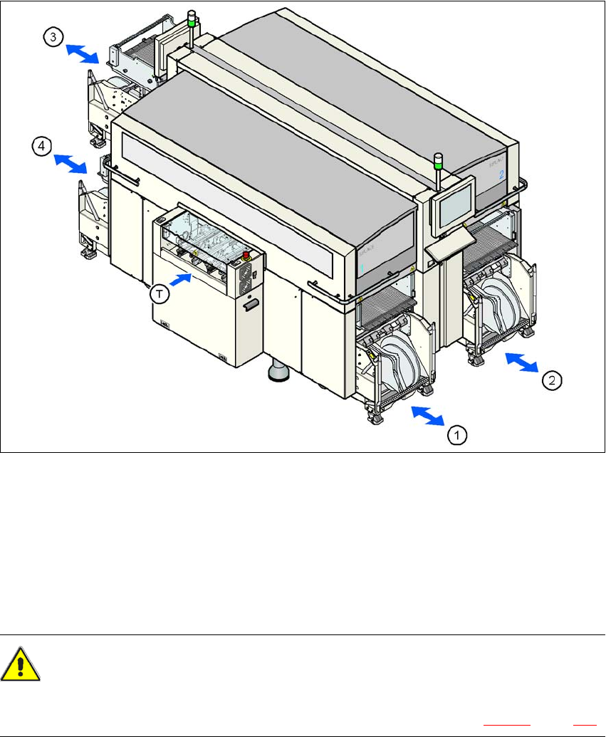
Up to four SIPLACE X-series component trolleys can be docked into the machines from the
SIPLACE X-series. The locations are numbered as shown in the diagram below.
3
Fig. 3.11 - 1 Component trolley locations, SIPLACE X-series
(1) Location 1
(2) Location 2
(3) Location 3
(4) Location 4
(T) PCB direction of travel
CAUTION 3
The component trolleys from the SIPLACE X-series may only be docked into locations at which
the component trolley docking unit for the SIPLACE X-series is installed (Fig. 5.11 - 3, page 360).
3 Technical data for the machine User Manual SIPLACE X-Series
3.11 SIPLACE X-series component trolley From software version SR.605.xx 07/2008 EN Edition
214
The component trolleys are stand-alone modules that can be set up with feeders at an external
set-up area. This means that the production process only has to be interrupted briefly in order to
change the component trolley.
3
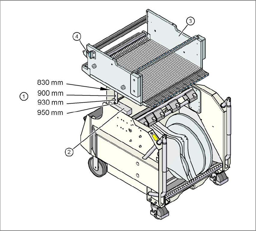
Fig. 3.11 - 2 Component trolley, SIPLACE X-series with a PCB conveyor height of 950 mm
3
(1) Holes for the PCB conveyor heights 900, 930 and 950 mm in the guide columns. For the
830 mm conveyor height, the component table lies on the block (2).
(2) Supporting block
(3) Component table
(4) Contact for switching the safety switch in the component trolley docking unit
User Manual SIPLACE X-Series 3 Technical data for the machine
From software version SR.605.xx 07/2008 EN Edition 3.11 SIPLACE X-series component trolley
215
3.11.1 Structure
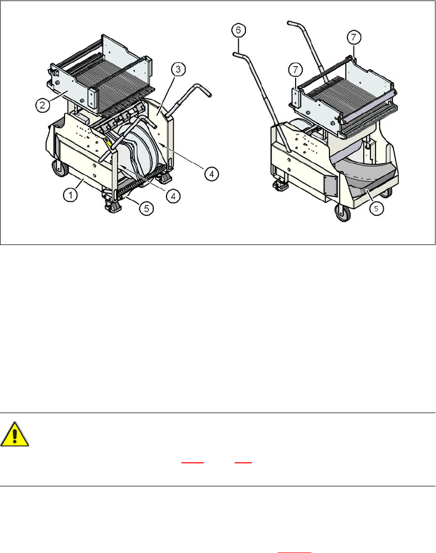
The component trolley essentially consists of the chassis, the component table for holding the
feeder modules, the tape reel container and the waste tape container.
3
Fig. 3.11 - 3 Component trolley, SIPLACE X-series, front and back view
(1) Chassis
(2) Component table
(3) Tape container
(4) Slot for holding set-up lists
(5) Waste tape container
(6) Handle
(7) Hand guard
CAUTION 3
Follow the safety instructions in Section 5.4.2
, page 331, when you pull the waste tape container
out of the component trolley.
3.11.2 Description
In the standard version, the tape reel container (item 3 in Fig. 3.11 - 3) holds tape reels up to 17"
(432 mm).