00195722-0102_UM_X-Serie_SR605_EN.pdf - 第225页
User Manual SIPLACE X-Series 3 Technical data for the machine From software version SR.605.xx 07/2008 EN Edition 3.12 SIPLACE HF component trolley 225 3.12 SIPLACE HF component trolley Item no. 001 19622-xx Component tro…
3 Technical data for the machine User Manual SIPLACE X-Series
3.11 SIPLACE X-series component trolley From software version SR.605.xx 07/2008 EN Edition
224
3.11.10 Used tape channel - CO trolley docking unit, SIPLACE X-series
In the standard version, the used tape channel can guide component tapes with a maximum
pocket height of 12 mm to the pneumatic tape cutter.
3
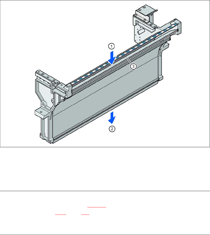
Fig. 3.11 - 11 Used tape channel - CO trolley docking unit, SIPLACE X-series
(1) Inlet slot for the used tapes
(2) Outlet slot for the used tape above the pneumatic tape cutter
(3) Dividing plate for tapes < 12 mm (can be removed for tapes > 12 mm)
PLEASE NOTE
– The separating plate (item 3 in Fig. 3.11 - 11
) can be removed for tape pockets higher than
12 mm (see Section 4.6.1
, page 315).
→ Do not position feeder modules with shallow pockets immediately beside feeder modules with
deep pockets. The used tapes could overlap and build up.
User Manual SIPLACE X-Series 3 Technical data for the machine
From software version SR.605.xx 07/2008 EN Edition 3.12 SIPLACE HF component trolley
225
3.12 SIPLACE HF component trolley
Item no. 00119622-xx Component trolley, SIPLACE HF/X-series/D3
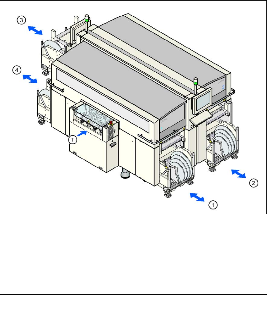
Up to four SIPLACE HF component trolleys can be docked into the machines from the SIPLACE
X-series. The locations are numbered as shown in the diagram below.
3
Fig. 3.12 - 1 Component trolley locations, SIPLACE HF
(1) Location 1
(2) Location 2
(3) Location 3
(4) Location 4
(T) PCB direction of travel
PLEASE NOTE 3
The SIPLACE HF component trolley cannot be used together with the 20-segment Collect&Place
head.
3 Technical data for the machine User Manual SIPLACE X-Series
3.12 SIPLACE HF component trolley From software version SR.605.xx 07/2008 EN Edition
226
CAUTION 3
The component trolleys from the SIPLACE HF may only be docked into locations at which the
component trolley docking unit for the SIPLACE HF is installed (Fig. 5.11 - 6, page 364).
The component trolleys are stand-alone modules that can be set up with feeders at an external
set-up area. This means that the production process only has to be interrupted briefly in order to
change the component trolley.
PLEASE NOTE:
At external set-up positions, you will need an external power supply for the component trolley
(see Section 3.12.6, page 231).
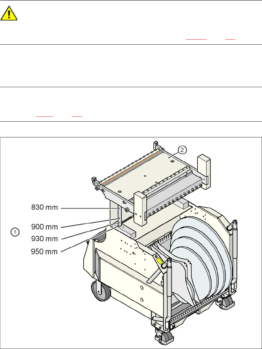
Fig. 3.12 - 2 SIPLACE HF component trolley with a PCB conveyor height of 950 mm
(1) Holes in the guide columns for the transport heights of 830 to 950 mm
(2) Component trolley table