00195722-0102_UM_X-Serie_SR605_EN.pdf - 第244页
4 Setting up and commissioning User Manual SIPLACE X-Series 4.1 Transport and Delivery Configuration From software version SR.605.xx 07/2008 EN Edition 244 Forks across the PCB conveyor 4 4 Fig. 4.1 - 4 Contact surfaces …
User Manual SIPLACE X-Series 4 Setting up and commissioning
From software version SR.605.xx 07/2008 EN Edition 4.1 Transport and Delivery Configuration
243
4
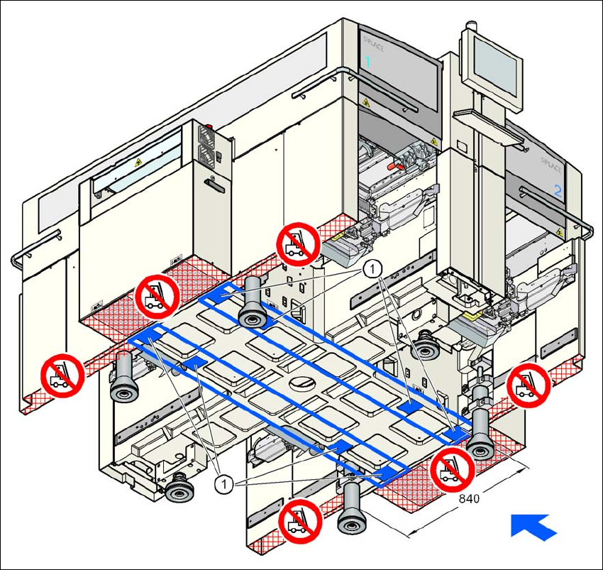
Fig. 4.1 - 3 Contact surfaces - Forks parallel to the direction of PCB transport
(1) Contact surfaces for the forks of the fork-lift
4 Setting up and commissioning User Manual SIPLACE X-Series
4.1 Transport and Delivery Configuration From software version SR.605.xx 07/2008 EN Edition
244
Forks across the PCB conveyor 4
4
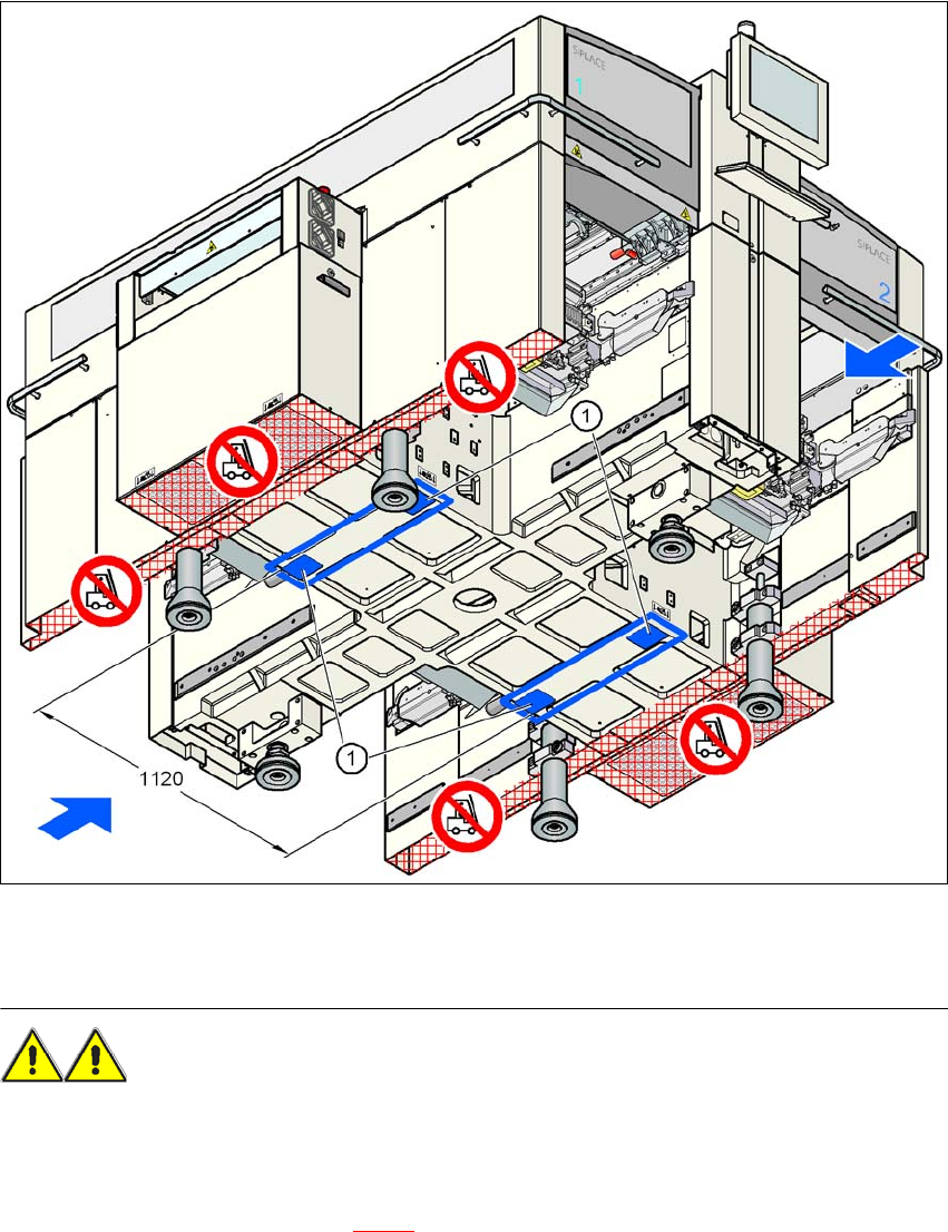
Fig. 4.1 - 4 Contact surfaces - Forks across the direction of PCB transport
(1) Contact surfaces for the forks of the fork-lift
WARNING 4
Please note the following points before you raise the placement machine in order to avoid irre-
versible damage to the machine:
– The distance between the forks must be between 800 and 900 mm. The attachment surfaces
for the fork-lift are shown in Fig. 4.1 - 4
. The maximum distance between the contact surfaces
is 1120 mm. NEVER increase the distance between the forks so that the machine is lifted on
the side parts of the machine frame, since this would deform the machine frame.

User Manual SIPLACE X-Series 4 Setting up and commissioning
From software version SR.605.xx 07/2008 EN Edition 4.2 Infrastructure at the installation location
245
→ Make sure that the forks are evenly loaded when you lift the machine. A firm support between
the forks and placement machine will prevent the machine tilting when it is raised. This will
also prevent a one-sided load on the machine feet, which would deform the fixing of the ma-
chine feet. We recommend that a second person watch the machine as it is raised, and make
sure that the machine does not tip to one side when lifted with the fork-lift.
4.1.5.4 Points that MUST be noted when transporting the machine
WARNING 4
When you are transporting the machine, make sure that all the feet are clear of the floor. If they
are not clear, the feet will drag along the floor or bump into obstacles. This could damage the
machine foot fixing in the machine frame.
4
4
4
4
4.2 Infrastructure at the installation location
4.2.1 Recommendations for the foundation quality
The foundation for the machine should be flat and level since dynamic forces can generate vibra-
tions at the installation site when the machine is in use. The magnitude of the vibrations depends
on the foundation construction. The following are suitable provided that the floor loading parame-
ters, etc., are not exceeded:
– Reinforced concrete ceiling constructions, e.g. ceilings in production halls
– Reinforced concrete floor slabs, e.g. concrete floors in production halls without a basement
– Rooms with double floors, provided that a stable foundation is included in the space between
them. The same set-up conditions apply to this intermediate foundation, which can be made
from steel girders or concrete.
4.2.1.1 Machine weight and floor loading
The machine weight and load per unit area values can be found in Section 3.3.1, page 109.
4