00195722-0102_UM_X-Serie_SR605_EN.pdf - 第249页
User Manual SIPLACE X-Series 4 Setting up and commissioning From software version SR.605.xx 07/2008 EN Edition 4.2 Infrastructure at the installation location 249 4.2.3.1 Danger notes W ARNING The placement system is sup…
4 Setting up and commissioning User Manual SIPLACE X-Series
4.2 Infrastructure at the installation location From software version SR.605.xx 07/2008 EN Edition
248
4.2.3 Main power supply
4
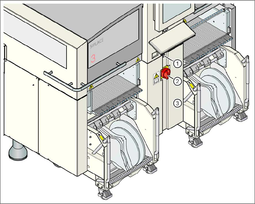
Fig. 4.2 - 2 Position of the power supply on the machine
4
(1) Lock
(2) Main power switch secured to prevent switching on again
(3) Cover
User Manual SIPLACE X-Series 4 Setting up and commissioning
From software version SR.605.xx 07/2008 EN Edition 4.2 Infrastructure at the installation location
249
4.2.3.1 Danger notes
WARNING
The placement system is supplied with 3 x 200 VAC, 3 x 208 VAC, 3 x 230 VAC, 3 x 380 VAC,
3 x 400 VAC or 3 x 415 VAC ± 5 %, 50/60 Hz mains voltage. This means that some parts of the
system carry potentially lethal voltages - even when switched off at the main power switch. Incor-
rect handling of the placement system can therefore result in death or severe injury or consider-
able damage to equipment. 4
→ Always follow the applicable accident prevention and DIN regulations (particularly DIN EN 60
204, part 1).
→ Only trained and qualified personnel may remove the cover over the power supply unit and
connect the machine to the power supply.
4
4
4.2.3.2 Checking the main power supply
Check that the main power supply conforms to the prescribed machine specifications (see table
in Section 3.2
, page 107).
PLEASE NOTE: 4
The document entitled "Network configuration (electrical and compressed air) for SMD systems
on the customer's premises", item no. 00191409-xx, describes the action that can be taken to
meet the required specifications.
PLEASE NOTE: 4
For technical reasons, load peaks occur in the power supply. Please contact your power com-
pany to clarify the mains impedance, if necessary.
4.2.3.3 Power supply cable - specification
The following specifications apply to the power supply cable:
5 x 6 mm² for 3 x 380 VAC / 3 x 400 VAC / 3 x 415 VAC
5 x 6 mm² for 3 x 200 VAC / 3 x 208 VAC / 3 x 230 VAC
The color coding for the wires will depend on the country in which the system is operated.
4 Setting up and commissioning User Manual SIPLACE X-Series
4.2 Infrastructure at the installation location From software version SR.605.xx 07/2008 EN Edition
250
WARNING 4
The electrical cables to each individual machine and to the installed options (e.g. MTC, produc-
tivity lift) must be clearly identified and there must be no doubt as to their allocation. The regula-
tions of the country in which the machine is operated apply.
4
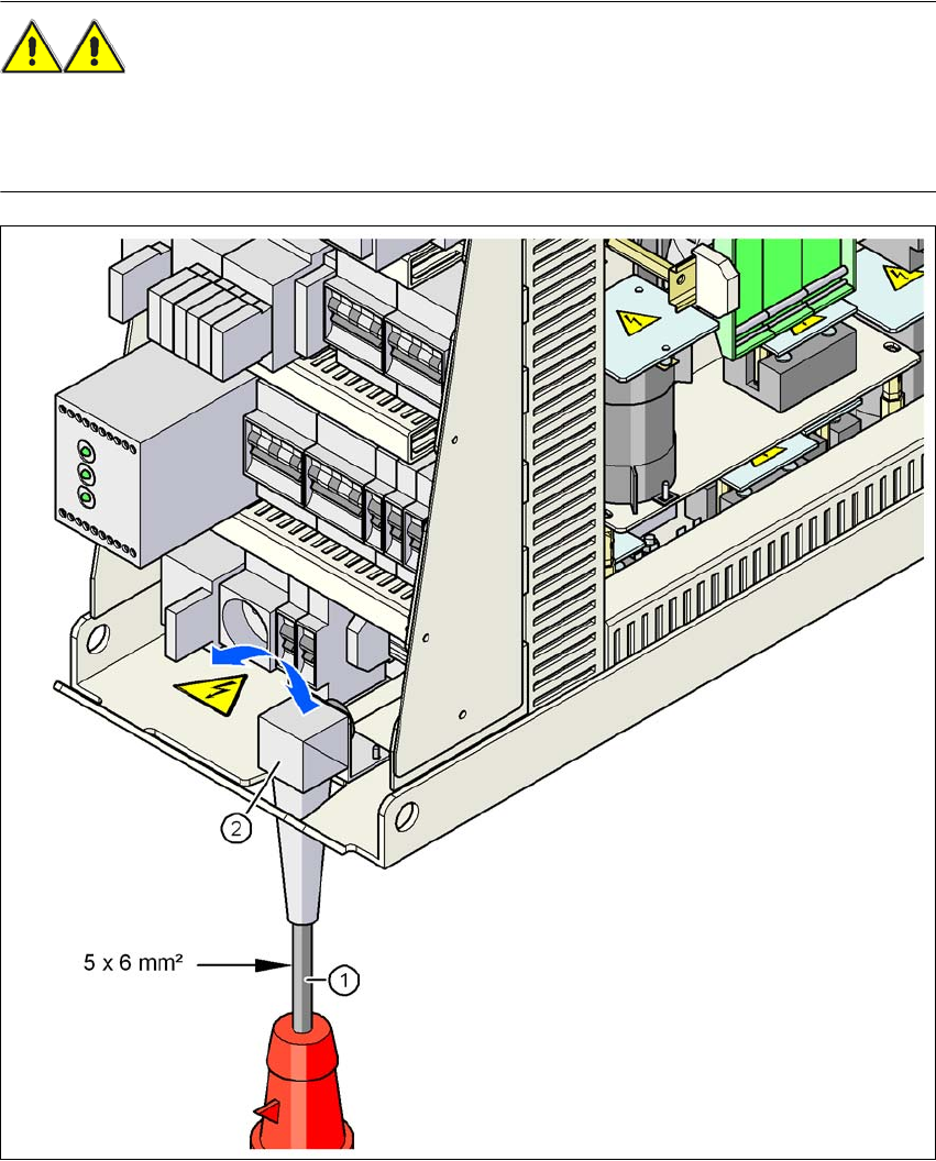
Fig. 4.2 - 3 Cross-section of the main power cable
(1) Power supply cable
(2) Angle for the cable gland