00195722-0102_UM_X-Serie_SR605_EN.pdf - 第287页
User Manual SIPLACE X-Series 4 Setting up and commissioning From software version SR.605.xx 07/2008 EN Edition 4.3 Setting up the placement machine 287 4.3.1 1 Fitting the box PC unit 4.3.1 1.1 Box PC unit - electrical c…
4 Setting up and commissioning User Manual SIPLACE X-Series
4.3 Setting up the placement machine From software version SR.605.xx 07/2008 EN Edition
286
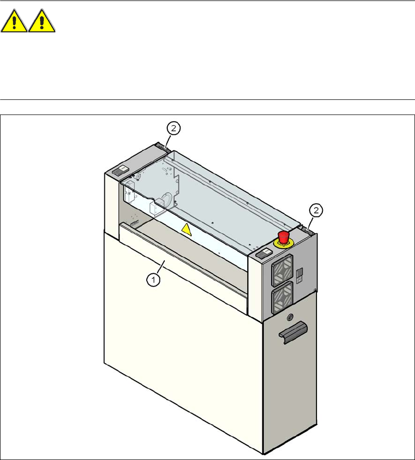
4.3.10.7 Fitting the "bottom" hand guard
The machines are supplied with just one "bottom" hand guard. If the machines are installed within
a line, then no hand guard is required between immediately adjacent output and input conveyors.
WARNING 4
Always fit the "bottom" hand guard (item no. 03045426-01) on the input side of the first place-
ment machine and on the output side of the last placement machine of a line using 4 hexagon
socket head screws M4x12. This will prevent your personnel reaching into the machine without
authorization.
4
Fig. 4.3 - 17 Fitting the "bottom" hand guard on the PCB output side
(1) "Bottom" hand guard, item no. 03045426-xx
(2) Protective cover switch
User Manual SIPLACE X-Series 4 Setting up and commissioning
From software version SR.605.xx 07/2008 EN Edition 4.3 Setting up the placement machine
287
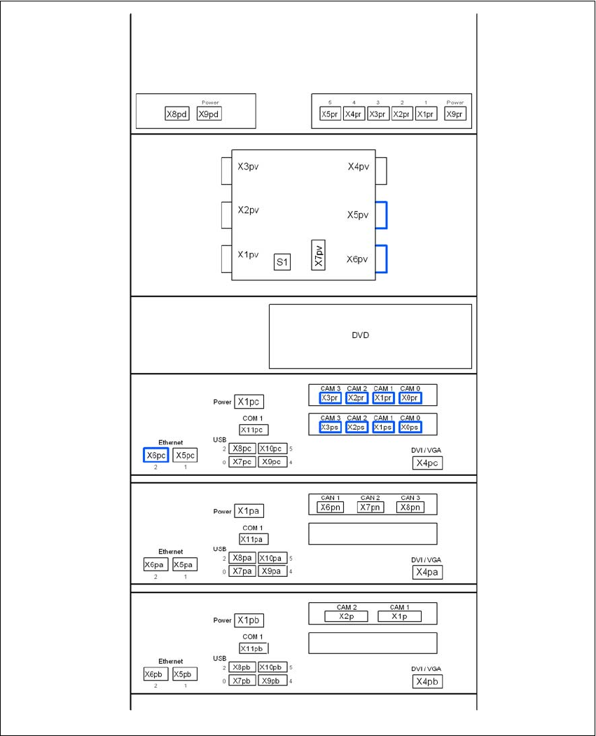
4.3.11 Fitting the box PC unit
4.3.11.1 Box PC unit - electrical connection points
4
Fig. 4.3 - 18 Box PC unit, front panel - connecting the plugs
USB hub
Ethernet switch
(3D sensor option)
Video multiplexer
Control computer
Machine controller
3D sensor computer option
4 Setting up and commissioning User Manual SIPLACE X-Series
4.3 Setting up the placement machine From software version SR.605.xx 07/2008 EN Edition
288
4
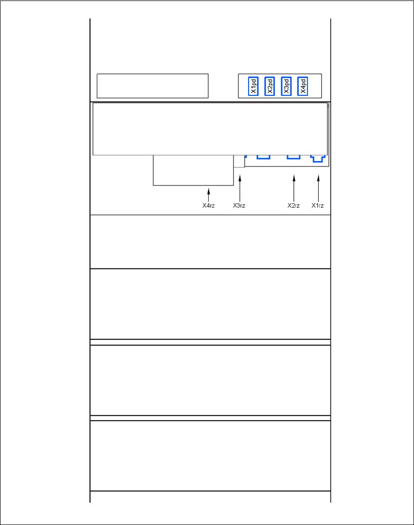
Fig. 4.3 - 19 Box PC unit, rear panel - connecting the plugs
USB hub
Ethernet switch
(3D sensor option)
DC/DC converter
Control computer
Machine controller
3D sensor computer option
Box PC voltage distributor