00195722-0102_UM_X-Serie_SR605_EN.pdf - 第290页
4 Setting up and commissioning User Manual SIPLACE X-Series 4.3 Setting up the placement machine From software version SR.605.xx 07/2008 EN Edition 290 4.3.1 1.3 Box PC unit X2, X3 a nd X4 - plug-in connectors on the rea…

User Manual SIPLACE X-Series 4 Setting up and commissioning
From software version SR.605.xx 07/2008 EN Edition 4.3 Setting up the placement machine
289
4.3.11.2 Box PC unit X2, X3 and X4 - plug-in connectors on the front panel
4
→ Also check the following plug-in connectors:
4
Box PC unit, front panel
(Fig. 4.3 - 18
, page 287)
Plug
Connecting cable NOTE
Plug Cable
X0pr
a
X0pr 03009778 Insert as far as the stop
X1pr
a
X1pr 03009838 Insert as far as the stop
X2pr
a
X2pr 03009755 Insert as far as the stop
X3pr
a
X3pr 03009756 Insert as far as the stop
X0ps
a
X0ps 03009798 Insert as far as the stop
X1ps
a
X1ps 03009818 Insert as far as the stop
X2ps
a
X2ps 03009757 Insert as far as the stop
X3ps
a
X3ps 03009758 Insert as far as the stop
X6pc X6pc 03010478 Insert as far as the stop
X5pv X5pv 03051749 Secure with screws
X6pv X6pv 03051750 Secure with screws
a) This plug is intended for cameras.
Box PC unit, front panel (Fig.
4.3 - 18
, page 287)
Plug
Plug Cable
X1pa X4rz (box PC rear panel) 03050908-W2
X1pc X4rz (box PC rear panel) 03050908-W1
X4pa X2pv 03051748
X4pc X1pv 03051747
X5pc X5pa 03051756
X7pc X8pd 03051755
X9pd X2rz (box PC rear panel) 03052633-W1

4 Setting up and commissioning User Manual SIPLACE X-Series
4.3 Setting up the placement machine From software version SR.605.xx 07/2008 EN Edition
290
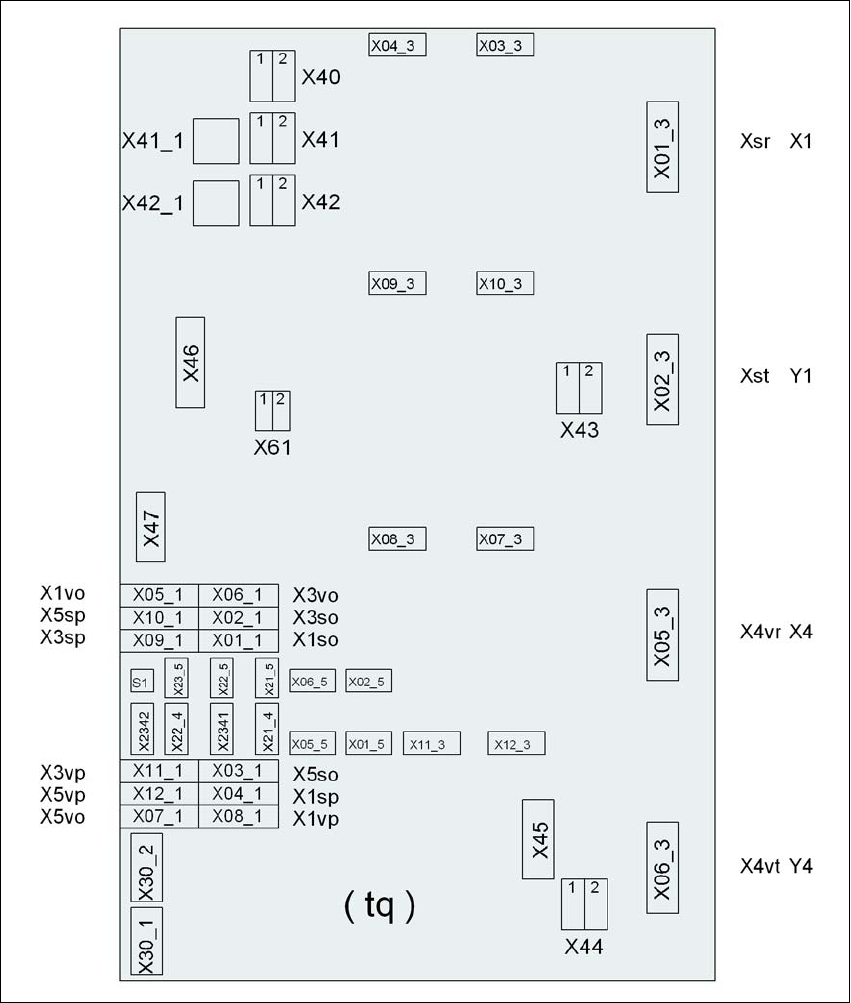
4.3.11.3 Box PC unit X2, X3 and X4 - plug-in connectors on the rear panel
4
4
4.3.11.4 Fitting the box PC unit
→ Plug in the plug-in connectors on the rear panel of the box PC unit (see Section 4.3.11.3, page
290
).
→ Carefully lift the box PC unit onto the rail in the extension kit.
→ Make sure that you do not squash any cables.
→ Push the box PC unit into the extension kit as far as the stop.
→ Plug in the plug-in connectors on the front panel of the box PC unit (see Section 4.3.11.2
,
page 289
).
→ Fix the cables to the front panel with cable ties.
→ Secure the box PC unit with the fillister head screw.
→ Fix the grounding cable to the doors (item 2 in Fig. 4.3 - 15
, page 282),
as shown in Fig. 4.3 - 16
on page 285.
→ Lock the doors.
PLEASE NOTE 4
On X2 placement machines, continue from Section 4.3.11.5
"Fitting the side plates".
On X3 and X4 placement machines, continue from Section 4.3.12
"Installing the axis unit" on
page 291.
4.3.11.5 Fitting the side plates
→ Fix the grounding cable to each side plate (item 6 in Fig. 4.3 - 15, page 282), as shown in Fig.
4.3 - 16
page 285.
→ Fix the side plate to the machine frame with 6 fillister head screws.
→ Continue from Section 4.3.13
"Fitting the indicator lamp", page 293.
Box PC unit, rear panel
(Fig. 4.3 - 19
, page 288)
Plug
Connecting cable NOTE
Plug Cable
PE1 Cable ring Grounding cable
Fix as shown in Fig. 4.3 - 16
,
page 285
.
X1rz X1rz 03051757 Insert as far as the stop
X3rz X3rz 03050907 Insert as far as the stop
X1pd X1pd 03051751 Insert as far as the stop
X2pd X2pd 03051752 Insert as far as the stop
X3pd X3pd 03051753 Insert as far as the stop
X4pd X4pd 03051754 Insert as far as the stop
User Manual SIPLACE X-Series 4 Setting up and commissioning
From software version SR.605.xx 07/2008 EN Edition 4.3 Setting up the placement machine
291
4.3.12 Installing the axis unit
4.3.12.1 Axis unit X3, X4 (gantry 1 and gantry 4) - electrical connection points
4
Fig. 4.3 - 20 Axis unit X3, X4 (gantry 1 and gantry 4), rear panel - connecting the plugs
Plug
Plug
Plug