00195722-0102_UM_X-Serie_SR605_EN.pdf - 第294页
4 Setting up and commissioning User Manual SIPLACE X-Series 4.3 Setting up the placement machine From software version SR.605.xx 07/2008 EN Edition 294 4 Fig. 4.3 - 21 Fitting the indicator lamp (1) Indicator lamp s (2) …

User Manual SIPLACE X-Series 4 Setting up and commissioning
From software version SR.605.xx 07/2008 EN Edition 4.3 Setting up the placement machine
293
4
→ Check the switch settings for S1
1: ON
2: Not used
4.3.12.3 Fitting the X3, X4 axis unit (gantry 1 and gantry 4)
→ Carefully lift the axis unit onto the rail in the extension kit.
→ Make sure that you do not squash any cables.
→ Push the axis unit into the extension kit as far as the stop.
→ Secure the axis unit with the fillister head screw.
→ Insert the cover.
→ Fix the grounding cable to the doors (item 2 in Fig. 4.3 - 15
, page 282),
as shown in Fig. 4.3 - 16
on page 285.
→ Lock the doors.
4.3.12.4 Fitting the side plates
→ Fix the grounding cable to each side plate (item 6 in Fig. 4.3 - 15, page 282), as shown in Fig.
4.3 - 16
page 285.
→ Fix the side plate to the machine frame with 6 fillister head screws.
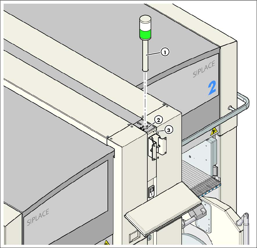
4.3.13 Fitting the indicator lamp
→ Connect the cables of the indicator lamps to the cables on the basic machine.
→ Insert the indicator lamp into the hole (item 2 in Fig. 4.3 - 21
, page 294) until the tube of the
indicator lamp projects sufficiently into the terminal beneath.
→ Tighten the hexagon socket head screw beneath the hole (item 3 in Fig. 4.3 - 21
, page 294).
X09_3tq X09_3tq 03050886 Snap connector into place
X10_3tq X10_3tq 03050885 Snap connector into place
X11_3tq X11_3tq 03050916 Snap connector into place
X12_3tq X12_3tq 03050915 Snap connector into place
X30_1tq
X30_2tq
X30_1tq
X30_2tq
03010051
03010051
Screw tightly
Axis unit, plugs Connecting cable NOTE
Plug Cable
4 Setting up and commissioning User Manual SIPLACE X-Series
4.3 Setting up the placement machine From software version SR.605.xx 07/2008 EN Edition
294
4
Fig. 4.3 - 21 Fitting the indicator lamp
(1) Indicator lamps
(2) Hole for the indicator lamp
(3) Hole for the locking screw
4.3.14 Fixing the monitors
→ Fix the monitors and connect the cables.
→ Check the cable connections
User Manual SIPLACE X-Series 4 Setting up and commissioning
From software version SR.605.xx 07/2008 EN Edition 4.3 Setting up the placement machine
295
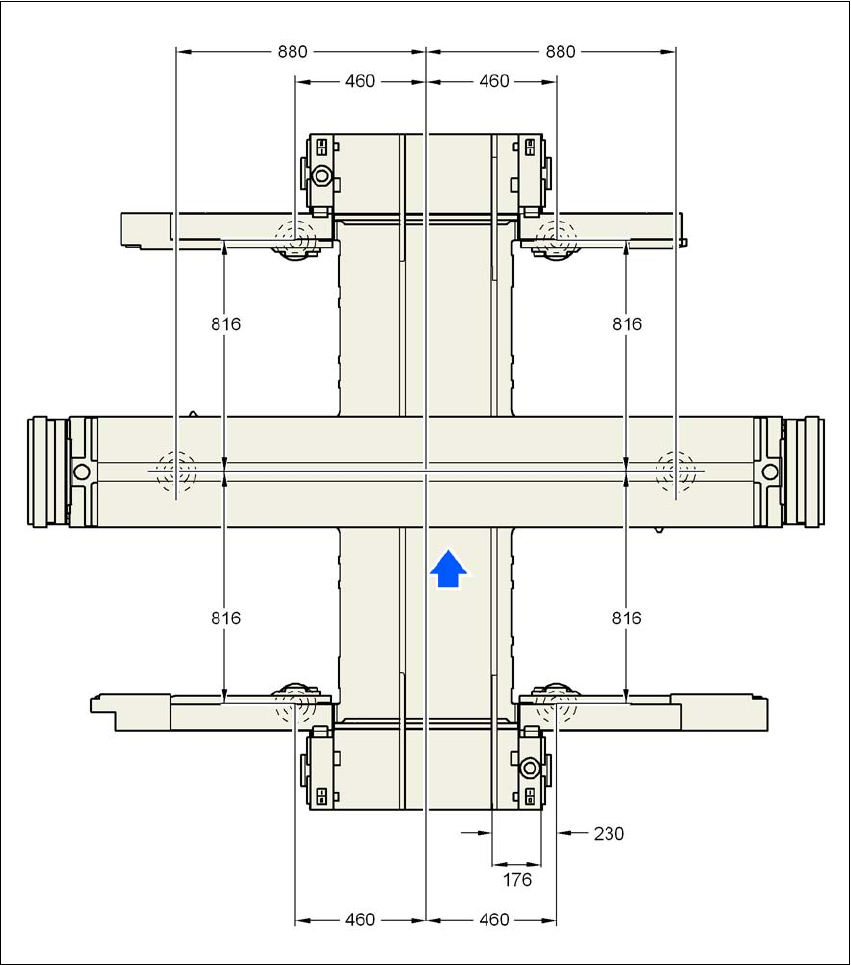
4.3.15 Machine foot clearances and the stationary PCB conveyor edges
4.3.15.1 Machine foot clearances and the stationary right conveyor edge for the
PCB single conveyor
4
Fig. 4.3 - 22 Machine foot clearances and the stationary right conveyor edge for the PCB single conveyor
in millimeters