00195722-0102_UM_X-Serie_SR605_EN.pdf - 第313页
User Manual SIPLACE X-Series 4 Setting up and commissioning From software version SR.605.xx 07/2008 EN Edition 4.4 A dapting the comp onent trolley to the PCB conveyor height 313 4 Fig. 4.4 - 4 Positions of the eye-bolt …
4 Setting up and commissioning User Manual SIPLACE X-Series
4.4 Adapting the component trolley to the PCB conveyor height From software version SR.605.xx 07/2008 EN Edition
312
4.4.2.1 Warning instructions
WARNING 4
Only SIPLACE engineers or qualified personnel are permitted to adjust the component trolley
height.
→ Always follow the applicable accident prevention regulations.
→ Remove all the feeder modules from the component table bed if you want to adjust the height
of the component table.
4.4.2.2 Tools and equipment
You will need the following tools and equipment to adjust the height of the component trolley:
–Hammer
– Punch, 8 mm
– Eye-bolt with M12 thread for lifting the component trolley table,
DIN 580 M12-St, item no. 00048350-xx
– Lifting device for raising the component trolley table, carrying capacity at least 80 kg
4.4.2.3 Changing the component trolley height
WARNING 4
Remove all the feeder modules from the component trolley table bed.
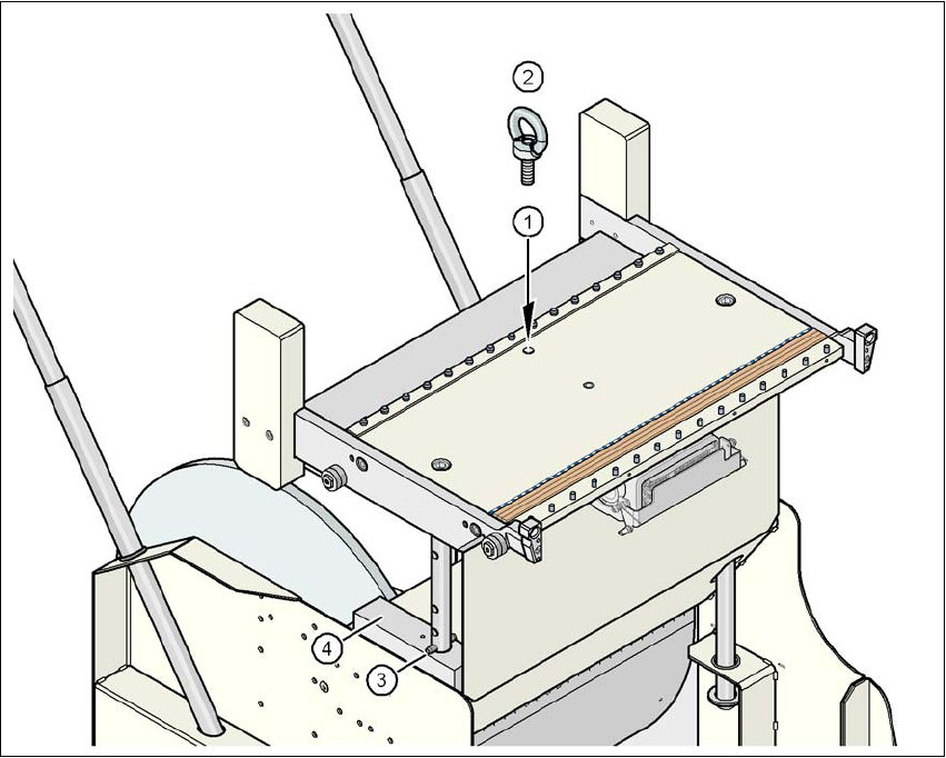
→ Screw the eye-bolt into the M12 hole (item 1 in Fig. 4.4 - 4
, page 313) in the component trolley
table bed.
→ Attach the hooks of the lifting device to the eye-bolt (item 2 in Fig. 4.4 - 4
, page 313).
→ Raise the component trolley bed slightly to expose the split pins (item 3 in Fig. 4.4 - 4
, page
313
).
→ Use the punch to carefully tap out the split pins on both sides.
→ Insert the spiral clamping pins into the holes for the required PCB conveyor height (see Fig.
4.4 - 3
, page 311).
→ Lower the component trolley bed slowly until the split pins lie on the supporting blocks (item
4 in Fig. 4.4 - 4
).
→ Unscrew the eye-bolt from the component trolley table.
User Manual SIPLACE X-Series 4 Setting up and commissioning
From software version SR.605.xx 07/2008 EN Edition 4.4 Adapting the component trolley to the PCB conveyor height
313
4
Fig. 4.4 - 4 Positions of the eye-bolt on the SIPLACE HF component trolley
(1) M12 hole for eye-bolt
(2) Eye-bolt, DIN 580 M12-St
(3) Spiral clamping pin, DIN 7343, 8x40 - St, 2x
(4) Supporting block, 2x
4 Setting up and commissioning User Manual SIPLACE X-Series
4.5 Adapting the used tape chute to the PCB conveyor height From software version SR.605.xx 07/2008 EN Edition
314
4.5 Adapting the used tape chute to the PCB conveyor
height
4.5.1 Adapting the SIPLACE X-series used tape chute to the PCB conveyor height
Depending on the PCB conveyor height, the length of the waste tape chute can be set so that the
pieces of tape are diverted directly into the waste tape container of the component trolley.
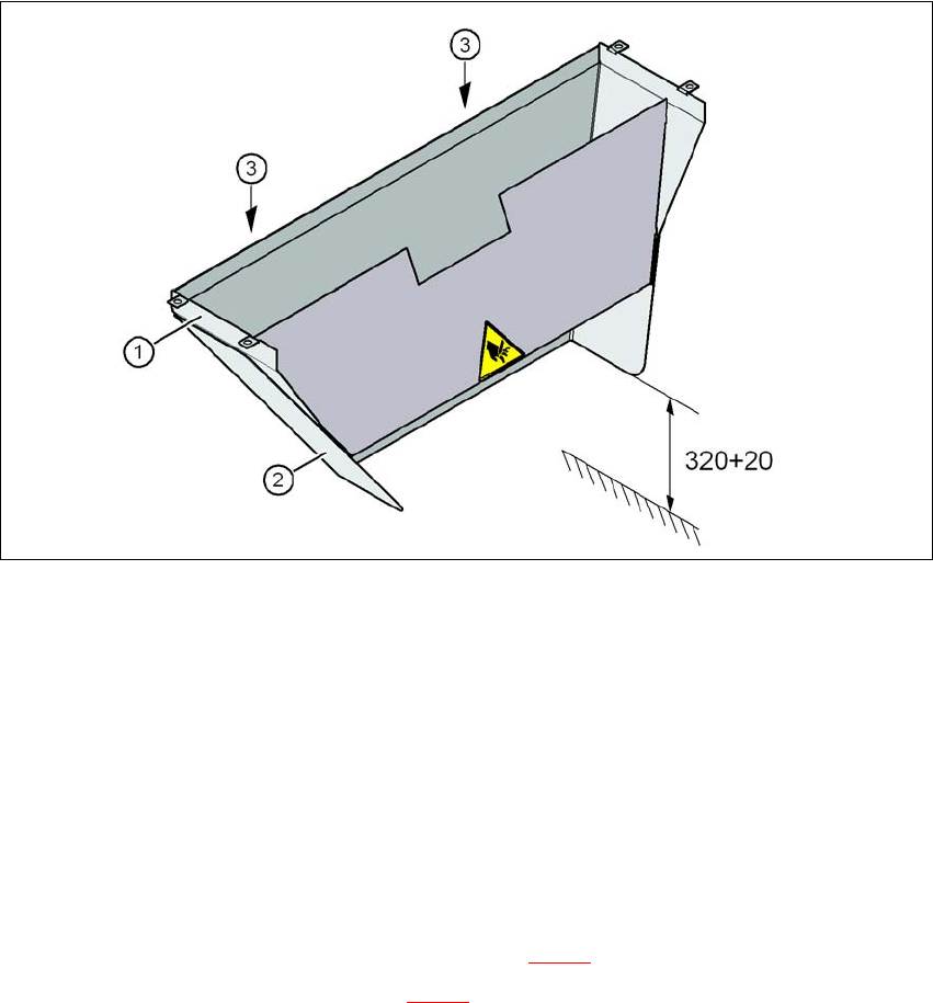
4
Fig. 4.5 - 1 Adapting the length of the used tape chute (X-series) - Dimensions in millimeters
(1) Used tape chute
(2) Extension
(3) Hexagonal nut M4, DIN 985, 2 x
4.5.1.1 Tools
– Fork wrench, size 7
4.5.1.2 Setting the used tape chute to PCB conveyor height of 830 mm
→ Loosen the two M4 hexagonal nuts (item 3 in Fig. 4.5 - 1).
→ Remove the extension (item 2 in Fig. 4.5 - 1
).