00195722-0102_UM_X-Serie_SR605_EN.pdf - 第338页
5 Tasks for the operating personnel User Manual SIPLACE X-Series 5.6 Setting up the feeder modules From software version SR.605.xx 07/200 8 EN Edition 338 5.6 Setting up the feeder modules 5.6.1 Notes on hand ling feeder…
User Manual SIPLACE X-Series 5 Tasks for the operating personnel
From software version SR.605.xx 07/2008 EN Edition 5.5 Carrying out a walk-through inspection
337
5.5.7 Using spindles for large tape reels
→ Insert spindles into the separating plates when using large tape reels on SIPLACE HF com-
ponent trolleys.
PLEASE NOTE 5
We recommend that you use spindles if the tape reel diameter exceeds 15" (381 mm)". This will
ensure that the S feeder modules operate reliably.
5
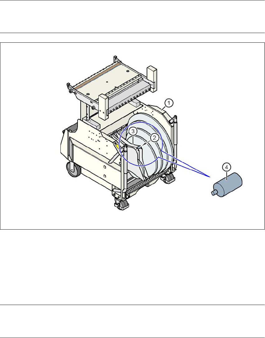
Fig. 5.5 - 5 Inserting spindles for large reels
5
(1) CO trolley
(2) Position of the spindles
(3) Separating plate
(4) Spindle (enlarged)
5
PLEASE NOTE: 5
X-series component trolleys do not generally need spindles. However, if the "Timeout" error mes-
sage occurs increasingly on the X feeder module, we recommend that you do use spindles.
5 Tasks for the operating personnel User Manual SIPLACE X-Series
5.6 Setting up the feeder modules From software version SR.605.xx 07/2008 EN Edition
338
5.6 Setting up the feeder modules
5.6.1 Notes on handling feeder modules
Feeder modules are precision devices. You should therefore handle the feeder modules with care.
→ Avoid bumping feeder modules into obstacles.
→ Do not drop the feeder modules.
→ Always use suitable tools for preventive maintenance.
5.6.2 Removing X feeder modules from the component table
5
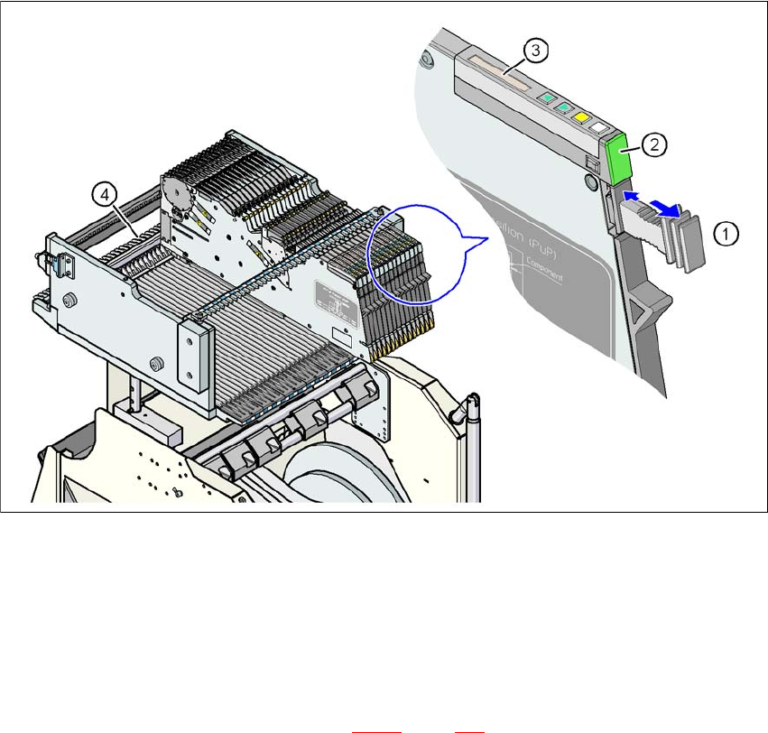
Fig. 5.6 - 1 Removing X feeder modules from the component table
(1) Removal handle
(2) Status display
(3) LCD display
(4) Latch for locking the X feeder modules
5
On standby, the status display (item 2 in Fig. 5.6 - 1, page 338) lights up green if the X-axis feeder
module is contained in the current set-up. If the feeder module is not contained in the current set-
up, the status display remains off.
User Manual SIPLACE X-Series 5 Tasks for the operating personnel
From software version SR.605.xx 07/2008 EN Edition 5.6 Setting up the feeder modules
339
The X feeder module is locked in position in the component table by a latch, and cannot be pulled
out. The procedure for removing feeder modules from the component table is as follows:
→ Press the removal handle (item 1 in Fig. 5.6 - 1
, page 338). The removal handle jumps
out and the status display goes out.
→ Wait approximately 1 second until the lock (item 4 in Fig. 5.6 - 1
, page 338) releases the
feeder module.
→ Use the removal handle to pull the feeder module out of the component table. If you wait
longer than 5 seconds, the feeder module will be locked once more. The status display
lights up red and the message "Handle --->>" appears on the LCD display (item 3 in Fig.
5.6 - 1
, page 338).
→ Engage the removal handle once more. If the X feeder module is contained in the current
set-up, the status display lights up green and the track number and increment are appear
on the LCD display once more.
→ Press the removal handle again (item 1 in Fig. 5.6 - 1
, page 338) and now pull the feeder
module out of the component table.
5
5
5.6.3 Using the X feeder module on the component trolley (X-series)
5.6.3.1 Check the X feeder module before using it
Check the following points before you use a feeder module on the component table:
→ The feeder module must be in perfect condition.
→ Tap the cover foil rocker (item 2 in Fig. 5.6 - 2
, page 340) lightly to make sure that it is not
jammed.
→ Check that the area around the pick-up window (item 3 in Fig. 5.6 - 2
, page 340) is free
from loose components.
PLEASE NOTE 5
Empty the component disposal compartment (item 5 in Fig.5.6 - 2
, page 340) before you
shake components out of the feeder module.
→ Push the lever (item 4 in Fig. 5.6 - 2
, page 340) forward slightly to open the pick-up win-
dow (item 3 in Fig. 5.6 - 2
, page 340). This will raise the pick-up window slightly.
PLEASE NOTE 5
Do not press the lever if a component tape is inserted. The tensioned cover foil would move
the component tape on and expose the components.
→ Remove any loose components from beneath the pick-up window.