00195722-0102_UM_X-Serie_SR605_EN.pdf - 第346页
5 Tasks for the operating personnel User Manual SIPLACE X-Series 5.6 Setting up the feeder modules From software version SR.605.xx 07/200 8 EN Edition 346 5.6.4.4 T ape support for 8 mm X t ape feeder module 5 Fig. 5.6 -…
User Manual SIPLACE X-Series 5 Tasks for the operating personnel
From software version SR.605.xx 07/2008 EN Edition 5.6 Setting up the feeder modules
345
→ Push the lever (item 5 in Fig. 5.6 - 5, page 344) forward in order to raise the pick-up window
(item 2 in Fig. 5.6 - 5
, page 344) into the first latching position.
→ Pull the cover foil at the side of the pick-up window forward and out underneath the pick-up
window.
→ Fold the cover foil back until it lies against the pull-off edge (item 3 in Fig. 5.6 - 5
, page 344).
PLEASE NOTE 5
Do not lower the pick-up window until the cover foil is lying against the pull-off edge.
→ Push the lever (item 5 in Fig. 5.6 - 5
, page 344) back to lower the pick-up window.
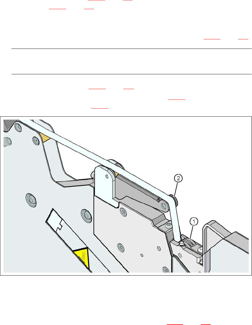
→ Guide the cover foil over the cover foil rocker (item 2 in Fig. 5.6 - 7
) until it reaches the foil
packing wheels (item 1 in Fig. 5.6 - 7
).
5
Fig. 5.6 - 7 Guiding the cover foil to the foil packing wheels
(1) Cover foil packing wheels
(2) cover foil
5
→ On the operator panel, press the FOIL button (item 3 in Fig. 5.6 - 6, page 344) until the cover
foil is tensioned. The cover foil rocker points down and stops the drive motor.
→ Cut the component tape flush with the front end of the feeder module.
5 Tasks for the operating personnel User Manual SIPLACE X-Series
5.6 Setting up the feeder modules From software version SR.605.xx 07/2008 EN Edition
346
5.6.4.4 Tape support for 8 mm X tape feeder module
5
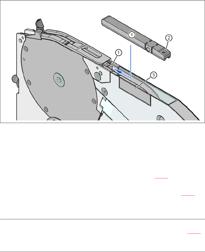
Fig. 5.6 - 8 8 mm X feeder module - tape support and splice sensor
(1) Tape support, removable
(2) Oval opening in the tape support
(3) Splice sensor installation location
The 8 mm X feeder module is equipped with a tape support (item 1 in Fig. 5.6 - 8
). It can easily be
removed if necessary.
→ Insert the tang of a watchmaker's screwdriver into the oval opening (item 2 in Fig. 5.6 - 8
) in
the tape support and pull the tape support out against the direction of travel of the tape.
→ When you insert the tape support, make sure that it engages in its desired position.
PLEASE NOTE 5
For all components size 0402 and smaller, always insert the tape support (item 1 in Fig. 5.6 - 8
)
into the 8 mm X feeder module. This will give you a constant Z pick up height and will minimize
the time needed to correct the pick up heights.

User Manual SIPLACE X-Series 5 Tasks for the operating personnel
From software version SR.605.xx 07/2008 EN Edition 5.6 Setting up the feeder modules
347
5.6.4.5 Splice sensors for X tape feeder modules
Splice sensors can be retrofitted to the X tape feeder modules. There are two versions of the sen-
sor:
Splice sensor for 8 mm and 12 mm X tape feeder modules
Splice sensor for 16 mm to 88 mm X tape feeder modules 5
The splice sensor is installed at the position indicated by item 3 in Fig. 5.6 - 8
, page 346.
Tape feeder modules with a splice sensor already installed can also be supplied (see Section
3.9.2
, from page 168).