00195722-0102_UM_X-Serie_SR605_EN.pdf - 第348页
5 Tasks for the operating personnel User Manual SIPLACE X-Series 5.6 Setting up the feeder modules From software version SR.605.xx 07/200 8 EN Edition 348 5.6.5 Using the S feeder module on the component trolley (HF-seri…

User Manual SIPLACE X-Series 5 Tasks for the operating personnel
From software version SR.605.xx 07/2008 EN Edition 5.6 Setting up the feeder modules
347
5.6.4.5 Splice sensors for X tape feeder modules
Splice sensors can be retrofitted to the X tape feeder modules. There are two versions of the sen-
sor:
Splice sensor for 8 mm and 12 mm X tape feeder modules
Splice sensor for 16 mm to 88 mm X tape feeder modules 5
The splice sensor is installed at the position indicated by item 3 in Fig. 5.6 - 8
, page 346.
Tape feeder modules with a splice sensor already installed can also be supplied (see Section
3.9.2
, from page 168).
5 Tasks for the operating personnel User Manual SIPLACE X-Series
5.6 Setting up the feeder modules From software version SR.605.xx 07/2008 EN Edition
348
5.6.5 Using the S feeder module on the component trolley (HF-series)
5
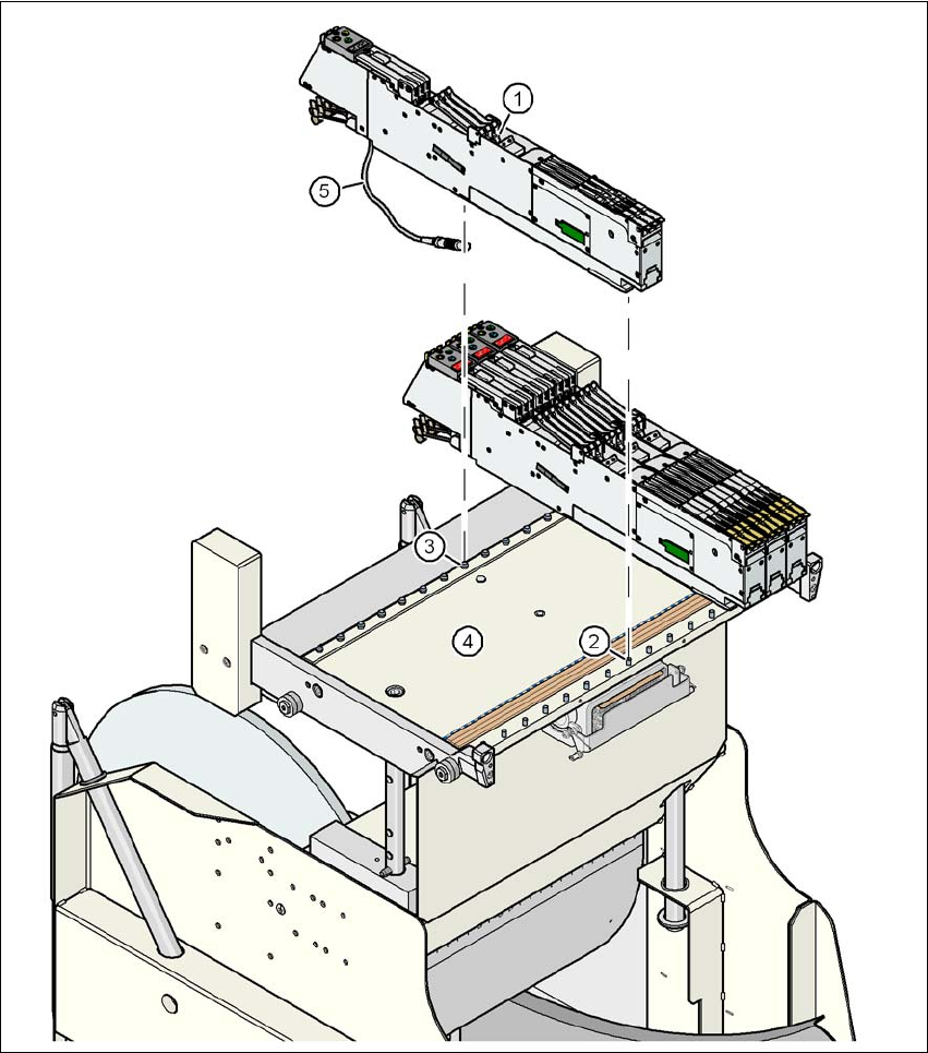
Fig. 5.6 - 9 CO trolley (HF-series) with 15 locations for S feeder modules
(1) S feeder module
(2) Centering pin
(3) Centering ball
(4) Component table
(5) Connecting cable for the S feeder module
User Manual SIPLACE X-Series 5 Tasks for the operating personnel
From software version SR.605.xx 07/2008 EN Edition 5.6 Setting up the feeder modules
349
5.6.5.1 Preparing the component table (SIPLACE HF) and S feeder modules for set-up
→ Clean the contact surface for the feeder module.
→ Clean the contact surface on the component table.
→ Remove loose components from the component table with a brush or use a vacuum cleaner
with appropriate nozzle.
CAUTION 5
Avoid removing components from the component table with your fingers. You may hurt your-
self with tiny splinters of metal.
5.6.5.2 Inserting the S feeder module
→ First place the front of the feeder module (item 1 in Fig. 5.6 - 9, page 348), i.e. the side with
the slotted foot, onto the component table (item 4 in Fig. 5.6 - 9
, page 348), so that the cen-
tering pin (item 2) on the component table slides into the slot in the feeder module foot.
→ Then lower the back of the feeder module until the centering ball (item 3 in Fig. 5.6 - 9
, page
348
) disappears completely into the hole in the feeder module.
→ Make sure that the feeder modules are placed correctly on the component table to suit their
width (see Fig. 5.6 - 10
, page 350).
→ Check that the feeder module is firmly seated on the component table. by tapping the side of
the feeder module with your finger. You should not be able to move it.
→ Connect the feeder module plug (item 5 in Fig. 5.6 - 9
, page 348) to the socket beneath the
location. The red dot on the plug must point towards the red dot on the socket.
PLEASE NOTE 5
When you connect the feeder module, make sure that you use the right socket for the location
since the feeder module receives the control pulse via this socket. The feeder module may
not work correctly if it is not connected to the right socket. The user manual for the feeder
modules used will contain detailed information on the assignment of plugs to sockets.