00195722-0102_UM_X-Serie_SR605_EN.pdf - 第374页
6 Station extensions User Manual SIPLACE X-Series 6.1 Nozzle changer From software version SR.605.xx 07/2008 EN Edition 374 6.1.1.6 Assembly "Row 1" nozzle changers (see Figs. 6.1 - 2 , 6.1 - 3 and 6.1 - 4 from…
User Manual SIPLACE X-Series 6 Station extensions
From software version SR.605.xx 07/2008 EN Edition 6.1 Nozzle changer
373
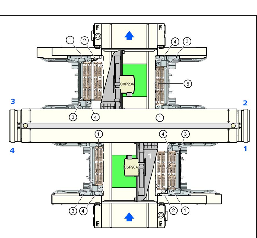
6.1.1.5 Position of the nozzle changers for the C&P20A head on the X2 machine
1 or 2 nozzle changers may be installed at locations 1 and 3 for the 20-segment Collect&Place
head (items 1 and 2 in Fig. 6.1 - 4
). A nozzle changer may be installed at locations 2 and 4. This
gives a total capacity of 6 nozzle changers with 36 magazines and a total of 432 nozzle holders.
6
Fig. 6.1 - 4 Position of the nozzle changer for the 20-segment Collect&Place head on the X2 machine
6
(1) Nozzle changer, "row 1"
(2) Nozzle changer, "row 2"
(3) Reject bin for components
(4) Take-off device and reject bin for nozzles
(5) Nozzle magazine
6 Station extensions User Manual SIPLACE X-Series
6.1 Nozzle changer From software version SR.605.xx 07/2008 EN Edition
374
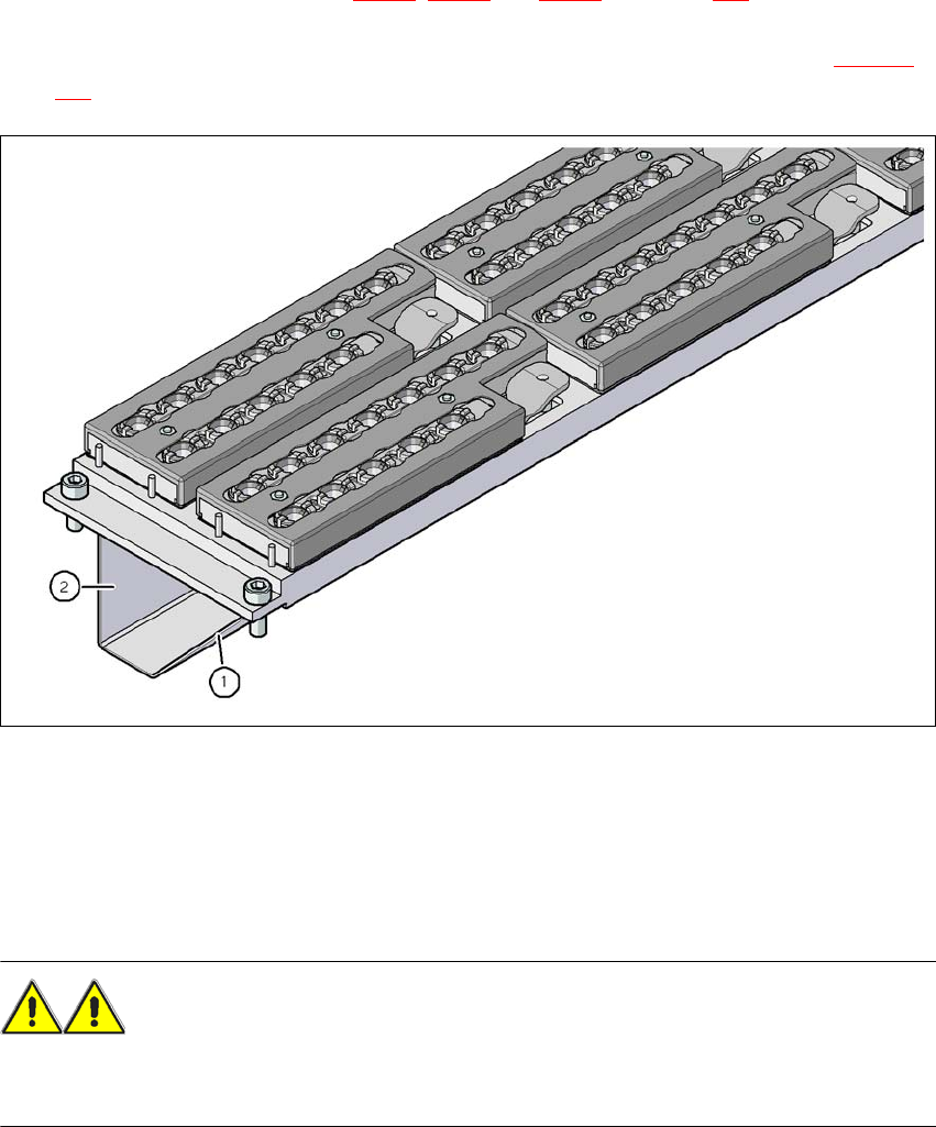
6.1.1.6 Assembly
"Row 1" nozzle changers (see Figs. 6.1 - 2, 6.1 - 3 and 6.1 - 4 from page 371) are each fixed to
the component trolley docking unit. There is an additional assembly kit for the "row 2" nozzle
changer. This kit consists of the take-off device and the nozzle reject bin (see Section 6.1.1.10
,
page 378
).
6
Fig. 6.1 - 5 Assembly position
(1) Sloping side points towards the component trolley docking unit
(2) Vertical side points towards the PCB conveyor
→ Align the nozzle changer so that the sloping side points towards the component trolley docking
unit.
WARNING 6
– Only install the associated nozzle changer for each placement head. There is a risk of head
crashes with mixed configurations.
User Manual SIPLACE X-Series 6 Station extensions
From software version SR.605.xx 07/2008 EN Edition 6.1 Nozzle changer
375
6.1.1.7 Notes on operation
→ When you fill a magazine with a certain nozzle type for the first time, attach an adhesive label
to identify the type.
PLEASE NOTE 6
Fill the magazines off the machine and always replace complete magazines. 6
→ Open the locking plate and place the nozzles in the nozzle holders.
→ Close the locking plate so that the nozzles cannot drop out of the magazines.
CAUTION 6
Before you fill magazine, make sure that all the nozzles on the Collect&Place head have
been returned to their magazines. 6
PLEASE NOTE 6
Do not allow components to drop onto the magazines. If they do, they could jam the locking
plate. You should therefore regularly clean the magazines and free locations.
→ Programming the nozzle changer is described in the SIPLACE Pro user manual.
6.1.1.8 Changing the magazine
→ Press the lever (item 1 in Fig. 6.1 - 6, page 373 to release the magazine from the balls of the
snap fasteners (item 5 in Fig. 6.1 - 6
, page 373). Lift the magazine off the base.