00195722-0102_UM_X-Serie_SR605_EN.pdf - 第404页
6 Station extensions User Manual SIPLACE X-Series 6.1 Nozzle changer From software version SR.605.xx 07/2008 EN Edition 404 – Grippers that grip the component at it s inner edge. Information on special nozzles and gripp …
User Manual SIPLACE X-Series 6 Station extensions
From software version SR.605.xx 07/2008 EN Edition 6.1 Nozzle changer
403
6.1.4.8 Nozzle changer 2 for the TwinHead
Item no. 00119717-xx Nozzle changer 2, TwinHead
This nozzle changer can hold up to 10 nozzle magazines. All the other technical data is the same
as for the 1st nozzle changer.
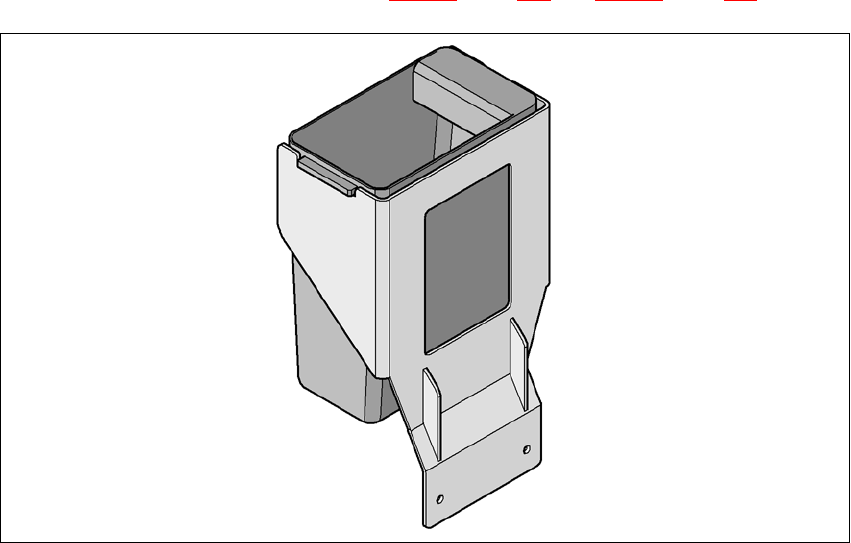
6.1.4.9 Component reject bin for the SIPLACE TwinHead
A component reject bin may be installed for the SIPLACE TwinHead. This is positioned beside the
fine-pitch vision module (see item 4 in Figs. 6.1 - 27
, page 399 and 6.1 - 28, page 400).
6
Fig. 6.1 - 31 Component reject bin for the SIPLACE TwinHead
6.1.4.10 Grippers and special nozzles
The SIPLACE placement machines can process components based on through hole technology
and odd-shaped (OSC) components, in addition to the standard SMT spectrum. SIPLACE also
continuously develops special nozzles and grippers in parallel.
Special nozzles are available for all placement heads in order to process placement jobs with max-
imum speed, precision and flexibility. The use of automatic nozzle changers also reduces the set-
up times that occur at a product change.
SIPLACE
can provide mechanical grippers for Pick&Place h
eads. If a component's surface is
not su
itable for sucking up with nozzles, then it can be picked up and placed with mechanical grip-
pers. There are two types of gripper, and their functions can be divided into two groups:
– Grippers that grip the component at its outer edges and
6 Station extensions User Manual SIPLACE X-Series
6.1 Nozzle changer From software version SR.605.xx 07/2008 EN Edition
404
– Grippers that grip the component at its inner edge.
Information on special nozzles and grippers is available from SIPLACE. For the production of
special magazines and grippers, again contact SIPLACE.
User Manual SIPLACE X-Series 6 Station extensions
From software version SR.605.xx 07/2008 EN Edition 6.2 Docking station for the component trolley from the SIPLACE X-series
405
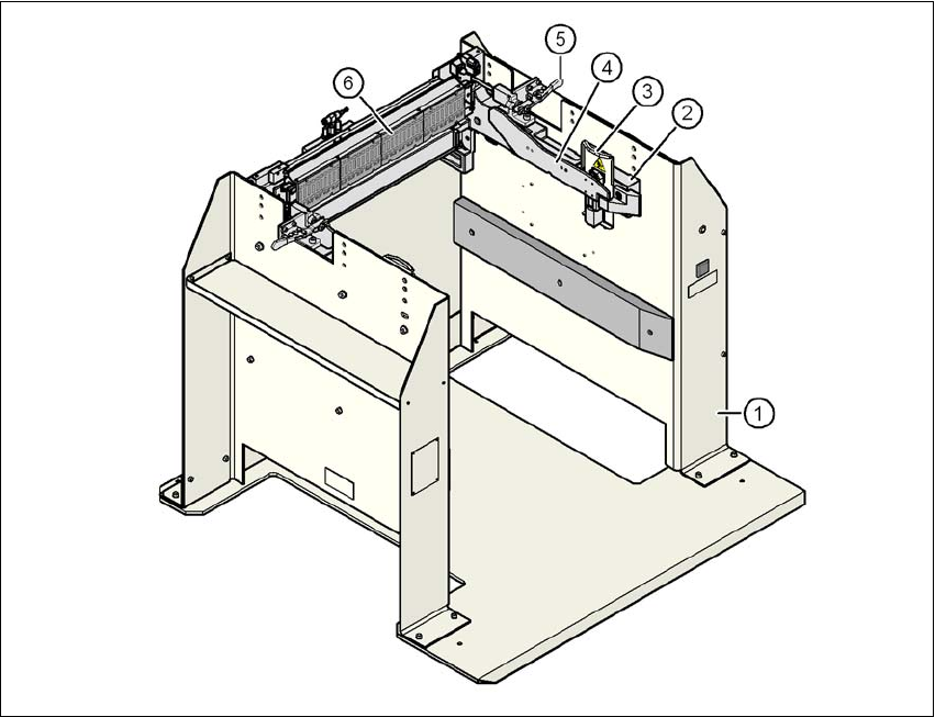
6.2 Docking station for the component trolley from the
SIPLACE X-series
Item no. 00116933-xx Docking station for the SIPLACE X component trolley
6.2.1 Description
The docking station is an additional component for the set-up area. It forms the link between the
set-up area and the component trolley for the SIPLACE X-series. The docking station allows the
component trolleys to be set up with feeder modules and function tests and set-up checks to be
carried out externally.
6
Fig. 6.2 - 1 Docking station, SIPLACE X-series
(1) Docking station
(2) Component trolley docking unit, X-series
(3) Guard plate with warning label W204
(4) Rails for guiding and docking in the component table
(5) Horizontal tensioner for locking the component trolley
(6) EDIF (energy and data interface)