00195722-0102_UM_X-Serie_SR605_EN.pdf - 第411页
User Manual SIPLACE X-Series 6 Station extensions From software version SR.605.xx 07/2008 EN Edition 6.2 Docking station for the component trolley fr om the SIPLACE X-series 411 6.2.5.1 T ools Y ou will need the followin…
6 Station extensions User Manual SIPLACE X-Series
6.2 Docking station for the component trolley from the SIPLACE X-series From software version SR.605.xx 07/2008 EN Edition
410
6.2.5 Adapting the docking station to the PCB conveyor height
The component trolley docking unit can be adjusted to PCB conveyor heights of 830 mm, 900 mm,
930 mm and 950 mm in just a few simple actions.
6
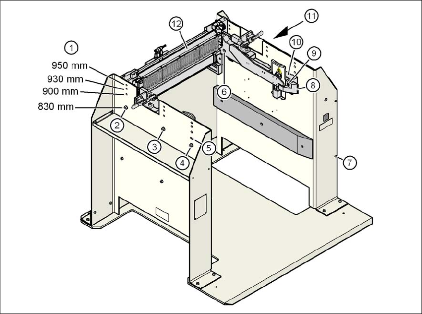
Fig. 6.2 - 5 Adapting the component trolley docking unit to the PCB conveyor heights
(1) Holes for the PCB conveyor height
(2) Hexagonal nut M8 and washer, 2x
(3) Hexagonal nut M8 and washer, 2x
(4) Hexagonal nut M8 and washer, 2x
(5) Slot for height adjustment
(6) Hexagon socket head screw M8x40, 6x
(7) Hexagon socket head screw M5x12, 4x
(8) Guide
(9) Hexagon socket head screw M8x18, 2x
(10) Side section, component trolley docking unit
(11) Panelling on the docking station
(12) Feeder module control unit (FCU)
User Manual SIPLACE X-Series 6 Station extensions
From software version SR.605.xx 07/2008 EN Edition 6.2 Docking station for the component trolley from the SIPLACE X-series
411
6.2.5.1 Tools
You will need the following tools and equipment to adjust the height for the component trolley
docking unit:
– Allen key, set
– Fork wrench, size 13
6.2.5.2 Converting the component trolley docking unit to other heights
WARNING 6
→ Disconnect the docking station from the main power supply.
→ Disconnect the docking station from the compressed air supply
The weight of the component trolley docking unit is approx. 40 kg.
→ Please ask a second person to help you with the conversion if necessary.
→ Note the order of the steps described.
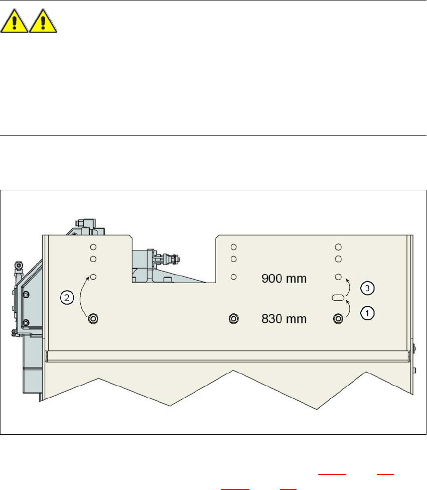
6.2.5.3 Converting the component trolley docking unit to a height of 830 mm or 900 mm
6
Fig. 6.2 - 6 Steps for conversion from a height of 830 mm to a height of 900 mm
→ Remove the two hexagon socket head screws M8x18 (item 9 in Fig. 6.2 - 5, page 410) and
remove the left and right guides (item 8 in Fig. 6.2 - 5
, page 410).
6
6 Station extensions User Manual SIPLACE X-Series
6.2 Docking station for the component trolley from the SIPLACE X-series From software version SR.605.xx 07/2008 EN Edition
412
PLEASE NOTE: 6
Only remove the panel (item 9 in Fig. 6.2 - 5
, page 410) in the following situations:
– You are converting the component trolley docking unit to a height of 830 mm.
– You are converting the component trolley docking unit height of 830 mm to another height.
→ Remove the 4 hexagon socket head screws M5x12 (item 7 in Fig. 6.2 - 5
, page 410). Hold the
panel tightly so that it does not drop down.
→ Remove the panel.
CAUTION 6
Be careful not to damage any cables while raising and lowering the component trolley docking
unit.
→ Release both screw connections (item 3 in Fig. 6.2 - 5
, page 410).
→ Loosen both screw connections (item 2 in Fig. 6.2 - 5
, page 410).
→ Remove both M8 hexagonal nuts and washers (item 4 in Fig. 6.2 - 5
, page 410).
→ Hold the component docking unit firmly at the side section (item 10 in Fig. 6.2 - 5
, page 410)
and remove both M8x40 hexagon socket head screws at this location.
→ Swivel the component trolley docking unit upwards until the hole in the side section is covered
with the slot (item 5 in Fig. 6.2 - 5
, page 410).
→ Fasten the side section at this location. Only hand-tighten the nuts.
→ Hold the component docking unit firmly at the FCU (item 12 in Fig. 6.2 - 5
, page 410) and re-
move the screw connections at item 2 in Fig. 6.2 - 5
, page 410.
→ Swivel the component trolley docking unit upwards until the hole in the side section is covered
with the 900 mm hole (item 1 in Fig. 6.2 - 5
, page 410).
→ Fasten the side section at this location. Only hand-tighten the nuts.
→ Swivel the component trolley docking unit from the slot (item 5 in Fig. 6.2 - 5
, page 410 to the
900 mm hole upwards and fixed in place firmly at this location.
→ Check all screw connections at items 2, 3 and 4 in the 900 mm component trolley height for
firm seating.
→ Fix the left and right guides (item 8 in Fig. 6.2 - 5
, page 410) using the hexagon socket head
screw M8x18 (item 9 in Fig. 6.2 - 5
, page 410).
→ Fix the panel (item 11 in Fig. 6.2 - 5
, page 410) using the 4 hexagon socket head screw M5x12
(item 7 in Fig. 6.2 - 5
, page 410) .