00195722-0102_UM_X-Serie_SR605_EN.pdf - 第440页
6 Station extensions User Manual SIPLACE X-Series 6.8 PCB barcode scanner Fr om software version SR.605.xx 07/2008 EN Edition 440 6.8.6.4 Positioning along the wid th of the PCB - Scanning beam across the direction of tr…
User Manual SIPLACE X-Series 6 Station extensions
From software version SR.605.xx 07/2008 EN Edition 6.8 PCB barcode scanner
439
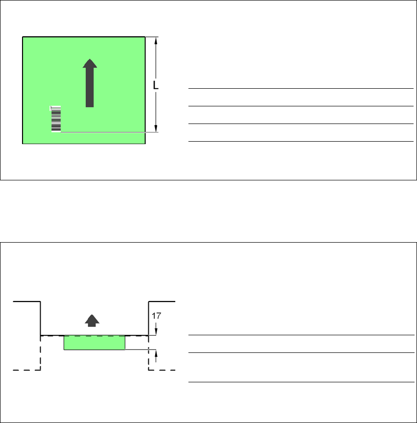
6.8.6.2 Positioning along the long side of the PCB -
Scanning beam along the direction of travel
Fig. 6.8 - 5 Positioning along the long side of the PCB - Scanning beam along the direction of travel
6.8.6.3 PCB overshoot over the machine with the dual conveyor
Fig. 6.8 - 6 PCB overshoot over the machine with the dual conveyor
PCB barcode scanner L [mm]
1D topside 320 - 350
1D underside 380 - 410
PCB barcode scanner Overshoot [mm]
2D underside on the
dual conveyor
17
Input side of the downstream machine
Output side of the upstream machine
6 Station extensions User Manual SIPLACE X-Series
6.8 PCB barcode scanner From software version SR.605.xx 07/2008 EN Edition
440
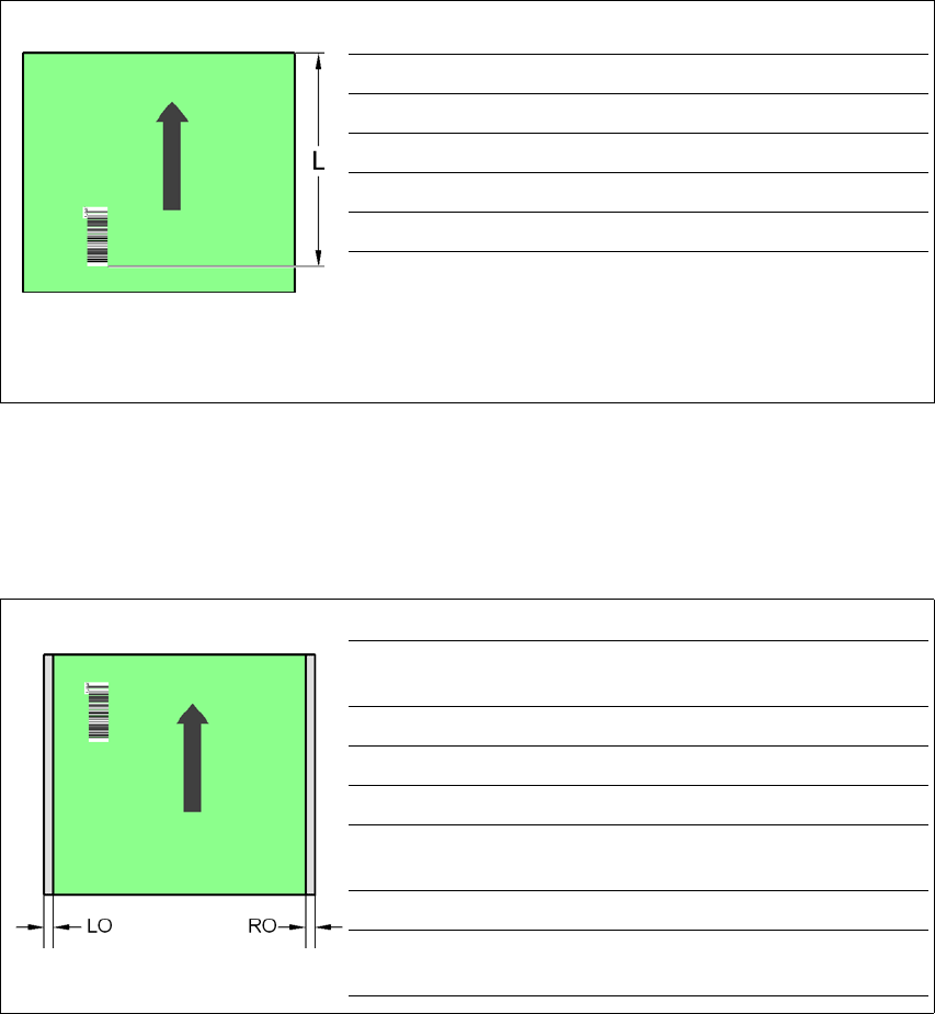
6.8.6.4 Positioning along the width of the PCB -
Scanning beam across the direction of travel
Fig. 6.8 - 7 Positioning along the width of the PCB - Scanning beam across the direction of travel
6.8.6.5 Positioning along the width of the PCB -
Scanning beam along the direction of travel,
PCB barcode scanner 1D topside
Fig. 6.8 - 8 Positioning along the width of the PCB - Scanning beam along the direction of travel
PCB barcode scanner 1D topside
PCB barcode scanner LQ [mm] RQ [mm]
2D topside 3 3
1D topside 3 3
2D underside
a
a) If there is a dual PCB conveyor installed on the placement ma-
chine, we can provide a special design for retrofitting
the 2D PCB barcode scanner "bottom.
55
1D underside 5 5
PCB dimensions/convey-
or
LO [mm] RO [mm]
460 mm / SC 3 20
508 mm / SC 3 44
216 mm / DC1 3 24
250 mm / DC1
450 mm / SM1
358
216 mm / DC2 3 3
250 mm / DC2
450 mm / SM2
33
User Manual SIPLACE X-Series 6 Station extensions
From software version SR.605.xx 07/2008 EN Edition 6.9 PCB alignment
441
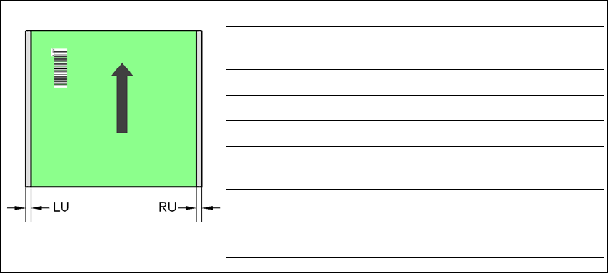
6.8.6.6 Positioning along the width of the PCB -
Scanning beam along the direction of travel,
PCB barcode scanner 1D underside
Fig. 6.8 - 9 Positioning along the width of the PCB - Scanning beam along the direction of travel
PCB barcode scanner 1D underside
SC Single conveyor
DC1 Dual conveyor, track 1
DC2 Dual conveyor, track 2
SM1 Dual conveyor in Single conveyor mode, track 1
SM2 Dual conveyor in Single conveyor mode, track 2
6
6.9 PCB alignment
Item no. 00119677-xx PCB alignment, single conveyor, SIPLACE HF/X/D3
Item no. 00119678-xx PCB alignment, dual conveyor, SIPLACE HF/X/D3
6.9.1 Description
PCBs to be processed sometimes have a length to width ratio of 1:2 or worse. This means that
the shorter side of the PCB points in the direction of travel. During travel, such PCBs may twist
slightly and, as a result, the fiducials no longer lie within the PCB vision camera's search window.
In this case, the "PCB alignment" option ensures that these PCBs are realigned precisely at the
stopping position.
If PCBs with recesses in the direction of travel are processed, this may result in different process-
ing positions on machines with mechanical stoppers (HS-50, S-25 HM, F5 HM) and on machines
PCB dimensions/convey-
or
LU [mm] RU [mm]
460 mm / SC 20 3
508 mm / SC 44 3
216 mm / DC1 3 3
250 mm / DC1
450 mm / SM1
33
216 mm / DC2 24 3
250 mm / DC2
450 mm / SM2
58 3