00195722-0102_UM_X-Serie_SR605_EN.pdf - 第451页
User Manual SIPLACE X-Series 6 Station extensions From software version SR.605.xx 07/2008 EN Edition 6.17 0201 package 451 6.17 0201 p ackage Item no. 001 19720-xx 0201 p ackage for C&P12, X/D seri es We can supply t…
6 Station extensions User Manual SIPLACE X-Series
6.16 High-resolution CO camera for the 12-segment C&P head, type 29 From software version SR.605.xx 07/2008 EN Edition
450
6.16 High-resolution CO camera for the 12-segment
C&P head, type 29
Item no. 00119779 High-resolution camera, C&P12, digital
6.16.1 Structure
6
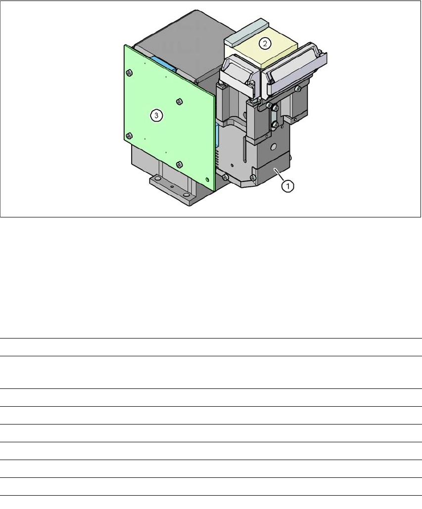
Fig. 6.16 - 1 C&P component camera, type 29, 27 x 27, digital
(1) Component camera lens and illumination
(2) Camera amplifier
(3) Illumination control
6.16.2 Technical data
6
Component dimensions 0.3 x 0.3 mm² to 18.7 x 18.7 mm²
Range of components 0201
a
to 18.7 x 18.7 mm², flip-chip, bare die, PLCC44, BGA, µBGA,
TSOP, QFP, SO to SO32, DRAM
Min. lead pitch 0.3 mm
Min. lead width 0.15 mm
Min. ball pitch 0.25 mm
Min. ball diameter 0.14 mm
Field of vision 32 x 32 mm²
Method of illumination Front-illumination (5 levels, programmable as required)
a) With 0201 package
User Manual SIPLACE X-Series 6 Station extensions
From software version SR.605.xx 07/2008 EN Edition 6.17 0201 package
451
6.17 0201 package
Item no. 00119720-xx 0201 package for C&P12, X/D series
We can supply the 0201 package for processing 0201 components with the 12-segment Col-
lect&Place head.
This contains:
– Component camera C&P (type 29), 27 x 27, digital, item no. 00119779
– Component sensor for the 12-segment C&P head, item no. 00118021
– 12 nozzles, type 706/906 Vectra ceramic, item no. 00345031
6.18 Coplanarity laser module
Item no. 00119719-xx Coplanarity module, SIPLACE X/D-series
6.18.1 Safety instructions for the sensor of the coplanarity module
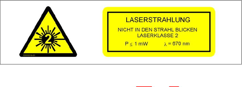
The sensor works with a semiconductor laser of wave length 670 nm (visible/red).
The maximum optical output is ≤ 1 mW.
The sensor is classified as laser class 2.
– When operating the sensor, always follow the relevant regulations of VDE 0837 concerning
"Radiation safety for laser equipment" and German accident prevention regulation entitled
"Laser radiation" (BGV B2).
– Also follow the accident prevention regulations applicable in your country.
The following information plates are attached to the front and back of the sensor housing:
6
Fig. 6.18 - 1 Identification of laser class 2 for the sensor
The working laser is signaled by an LED (see Section 6.18.6, page 455).
6 Station extensions User Manual SIPLACE X-Series
6.18 Coplanarity laser module From software version SR.605.xx 07/2008 EN Edition
452
NEVER look directly into the laser beam, despite the low laser output. The beam is visible, so the
eyes will be protected by the natural eyelid-closing reflex.
WARNING 6
Only authorized personnel may open the housing of the optical sensor.
For repair and servicing, always return the sensors to SIPLACE.
6.18.2 Description
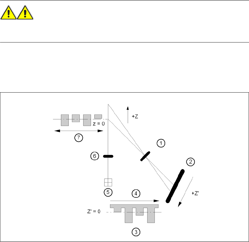
The coplanarity laser module is used to measure vertical bending of the leads. The lead length is
measured without contact using the laser triangulation principle.
6
Fig. 6.18 - 2 Laser triangulation measurement principle
(1) Receiver lens
(2) Detector
(3) Measuring signal
(4) Time t
(5) Laser
(6) Transmitter lens
(7) Travel direction