00195722-0102_UM_X-Serie_SR605_EN.pdf - 第457页
User Manual SIPLACE X-Series 6 Station extensions From software version SR.605.xx 07/2008 EN Edition 6.19 3D coplanarity laser module 457 6.19 3D coplanarity laser module Item no. 001 19919-xx 3D coplan arity sensor 6.19…

6 Station extensions User Manual SIPLACE X-Series
6.18 Coplanarity laser module From software version SR.605.xx 07/2008 EN Edition
456
Red
Outside the measuring range,
with low reflection
LED Off Laser switched off
LED Power Status display
LED lights up Supply voltage present
LED avg avg1 avg2
Off Off No averaging
Red Off Averaging 1
Off Red Averaging 2
Red Red Averaging 3
LED state Status display
User Manual SIPLACE X-Series 6 Station extensions
From software version SR.605.xx 07/2008 EN Edition 6.19 3D coplanarity laser module
457
6.19 3D coplanarity laser module
Item no. 00119919-xx 3D coplanarity sensor
6.19.1 Safety instructions
The safety instructions are the same as described for the 2D coplanarity laser module in Section
6.18
, page 451.
6.19.2 Description
The 3D coplanarity laser module no longer works with a dot-shaped laser light source. It now re-
quires a laser light line. The measuring process is based on the principle of triangulation (see Fig.
6.18 - 2
, page 452). This makes it possible to generate and analyze a height profile for a two-di-
mensional arrangement of component connections, e.g. BGA, QFP, et. The analysis returns re-
sults for the coplanarity (placement plane) and colinearity (placement line) of component leads or
balls. The 3D coplanarity laser module can be installed on SIPLACE X2 and X3 placement ma-
chines.
6
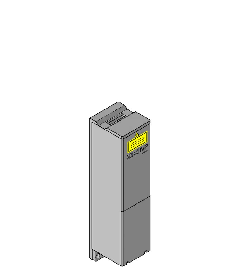
Fig. 6.19 - 1 3D coplanarity laser module

6 Station extensions User Manual SIPLACE X-Series
6.19 3D coplanarity laser module From software version SR.605.xx 07/2008 EN Edition
458
6.19.3 Technical data
6
6.19.4 Restrictions
– Lead or ball recognition can get worse if the surface is oxidized or glossy.
– The following components cannot be measured: a PLCC, SOJ, socket, chip, bare die,
Moulded, Melf, ECV, DPack, CCGA, screening plate, components which only have connec-
tions on the underside
6.19.5 Installation notes
Please note the following points if you are installing the 3D coplanarity laser module:
– The 3D coplanarity laser module can only be installed on SIPLACE machines that are
equipped with the A364 axis unit and the Box PC. It cannot be retrofitted on machines with
the A363 axis unit.
Components QFP, SO, BGA, gull-wing, plug
Accuracy
a
± 15 μm (3σ), ± 20 μm (4σ)
Maximum component size 50 x 50 mm²
Maximum component height 17 mm
Package forms BGA
Min. ball diameter
Min. ball pitch
Min. number of balls
400 μm
800 μm
6
Package forms Gullwing
Min. lead width
b
Min. ball pitch
Min. number of balls
300 μm
500 μm
5
Max. plug size 120 x 20 mm²
Plug (Gullwing)
Min. lead width
b
Min. ball pitch
Min. number of balls
300 μm
500 μm
5
Placement head type TwinHead
Laser protection class
3D coplanarity sensor
Placement machine
3B
2
a) Per ball / lead
b) Please contact your local product manager in the case of smaller lead widths