00195722-0102_UM_X-Serie_SR605_EN.pdf - 第459页
User Manual SIPLACE X-Series 6 Station extensions From software version SR.605.xx 07/2008 EN Edition 6.19 3D coplanarity laser module 459 – Only one coplanarity laser module may be installed on each machine. The 3D copla…

6 Station extensions User Manual SIPLACE X-Series
6.19 3D coplanarity laser module From software version SR.605.xx 07/2008 EN Edition
458
6.19.3 Technical data
6
6.19.4 Restrictions
– Lead or ball recognition can get worse if the surface is oxidized or glossy.
– The following components cannot be measured: a PLCC, SOJ, socket, chip, bare die,
Moulded, Melf, ECV, DPack, CCGA, screening plate, components which only have connec-
tions on the underside
6.19.5 Installation notes
Please note the following points if you are installing the 3D coplanarity laser module:
– The 3D coplanarity laser module can only be installed on SIPLACE machines that are
equipped with the A364 axis unit and the Box PC. It cannot be retrofitted on machines with
the A363 axis unit.
Components QFP, SO, BGA, gull-wing, plug
Accuracy
a
± 15 μm (3σ), ± 20 μm (4σ)
Maximum component size 50 x 50 mm²
Maximum component height 17 mm
Package forms BGA
Min. ball diameter
Min. ball pitch
Min. number of balls
400 μm
800 μm
6
Package forms Gullwing
Min. lead width
b
Min. ball pitch
Min. number of balls
300 μm
500 μm
5
Max. plug size 120 x 20 mm²
Plug (Gullwing)
Min. lead width
b
Min. ball pitch
Min. number of balls
300 μm
500 μm
5
Placement head type TwinHead
Laser protection class
3D coplanarity sensor
Placement machine
3B
2
a) Per ball / lead
b) Please contact your local product manager in the case of smaller lead widths
User Manual SIPLACE X-Series 6 Station extensions
From software version SR.605.xx 07/2008 EN Edition 6.19 3D coplanarity laser module
459
– Only one coplanarity laser module may be installed on each machine. The 3D coplanarity la-
ser module can therefore not be operated together with the previous module (see Section
6.18
, page 451).
– The 3D coplanarity laser module can only be installed at location 3.
– The 3D coplanarity laser module can only be used in conjunction with the TwinHead.
– The 3D coplanarity laser module cannot be set up if there is a Collect&Place head installed
in this placement area.
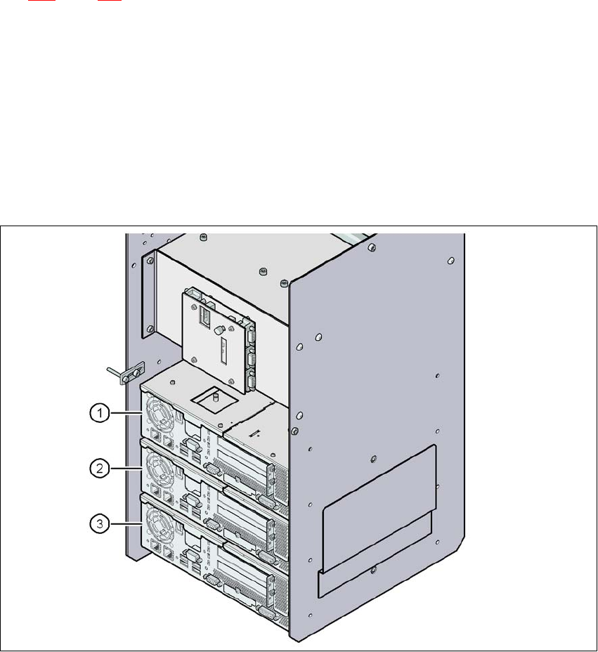
6.19.6 Analysis computer
A box PC acts as an analysis computer. It is housed together with the control computer and the
machine controller on the input side.
6
Fig. 6.19 - 2 Box PC for the 3D coplanarity laser module
(1) Control computer
(2) Machine controller
(3) Analysis computer for the 3D coplanarity laser module
6 Station extensions User Manual SIPLACE X-Series
6.20 SIPLACE Productivity Lift From software version SR.605.xx 07/2008 EN Edition
460
6.20 SIPLACE Productivity Lift
Item no. 00119314-xx Productivity Lift, underfloor section of dual conveyor
Item no. 00116325-xx Productivity Lift, HV shuttle with dual conveyor, emergency belt
Item no. 00116310-xx Productivity Lift, HV shuttle with single conveyor, emergency belt
Item no. 00119316-xx Productivity Lift, underfloor section of single conveyor
Item no. 00116326-xx Productivity Lift, V shuttle with single conveyor, emergency belt
Item no. 00116316-xx Productivity Lift accessory package 1 (1 x per line if an open conveyor
belt is used without safety cover upstream or downstream of a SI-
PLACE Productivity Lift)
Item no. 00116317-xx Productivity Lift accessory package 2 (1 x per line if an open conveyor
belt is used with safety cover upstream or downstream of a SIPLACE
Productivity Lift)
Item no. 00119635-xx Productivity Lift accessory package for HF or X-series (for incorporat-
ing the placement machine into the safety circuit of the SIPLACE Pro-
ductivity Lift)
6.20.1 Concept of parallel placement
Placement lines are generally arranged in series and are linked to one another serially. The
placement program is processed sequentially while the PCBs are transported from one machine
to the next. This means that the placement of a PCB is distributed between various machines.
When machines are connected in parallel, the components to be placed by individual machines
are combined. Several machines work through the same placement program. They place all the
components on one machine that would be distributed between several machines with serial pro-
cessing. When one machine runs out of capacity, the PCBs are moved to and placed at the next
machine with the same placement program. This combination of machines with the same compo-
nents to be placed is known as a group or “cluster”.
6.20.2 Implementing parallel placement
Lines with machines arranged in parallel take up a lot more space, so the parallel placement con-
cept was implemented with an underfloor conveyor and horizontal / vertical lift (HV shuttle). The
machines are still arranged in series, but the lift units and underfloor conveyors allow the line to
be operated in parallel. In this way, SIPLACE lines remain almost as compact as before.