00195722-0102_UM_X-Serie_SR605_EN.pdf - 第63页
User Manual SIPLACE X-Series 2 Operational safety From software version SR.605.xx 07/2008 EN Edition 2.4 Safety instructions for transporting the machine 63 2.3.3 Laser class 2 The following modules are assi gned to lase…
2 Operational safety User Manual SIPLACE X-Series
2.3 Laser classification From software version SR.605.xx 07/2008 EN Edition
62
2.3 Laser classification
2.3.1 Laser class 1
2.3.1.1 Classification of the whole machine
2
PLEASE NOTE: 2
Modules in laser classes 1 and 1M are not identified.
2.3.1.2 Classification of the camera systems
2
2.3.2 Laser class 1M
Do not look directly at this with optical instruments!
2
2
All installed camera systems and the whole machine when ready
for operation are assigned to laser class 1.
The laser classes are determined according to DIN EN 60825-
1:2001.
2
The following camera systems are assigned to laser class 1:
– Component cameras for the SIPLACE TwinHead
Stationary P&P component camera, type 33, 55 x 45, digital
Stationary P&P component camera, type 25, 16 x 16, digital
2
The following camera systems are assigned to laser class 1M:
– C&P CO camera, type 23, 6 x 6 on the 20-segment Collect&Place head
– C&P CO camera, type 28, 18 x 18 on the 12-segment Collect&Place head
– C&P CO camera, type 29, 27 x 27 on the 12-segment Collect&Place head
– C&P CO camera , type 29, 27 x 27 on the 6-segment Collect&Place head
User Manual SIPLACE X-Series 2 Operational safety
From software version SR.605.xx 07/2008 EN Edition 2.4 Safety instructions for transporting the machine
63
2.3.3 Laser class 2
The following modules are assigned to laser class 2:
– Laser light barrier, placement area 1 in the PCB conveyor
– Laser light barrier, placement area 2 in the PCB conveyor
– PCB barcode scanner
– Component sensor on the 20-segment Collect&Place head
– Coplanarity laser module
– 3D coplanarity laser module
(The entire machine is classified as laser class 2 if the coplanarity laser module option is installed.)
2
2.4 Safety instructions for transporting the machine
2
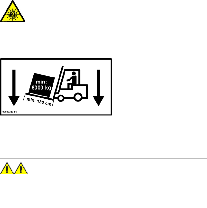
Use a fork-lift truck with the following specification to carry the machine:
Fork length: min. 1800 mm
Carrying power: min. 6000 kg
Clear width between forks: min. 350 mm 2
WARNING
RISK OF TIPPING 2
If the required specification cannot be applied to the fork-lift, there is a risk that the fork-lift will tip
over when carrying the placement machine.
Transporting the placement machine is described in chapter 4, Section 4.1, page 237.
2
Laser radiation
Do not look into beam!
2 Operational safety User Manual SIPLACE X-Series
2.5 Safety instructions for operating the machine From software version SR.605.xx 07/2008 EN Edition
64
2.5 Safety instructions for operating the machine
2.5.1 Safety instructions for closing the protective covers
To prevent any risk of injury when the protective covers on automatic placement machines are
closed, the owner must instruct his operators to use the protective covers exactly as specified in
the following instructions.
CAUTION
RISK OF CRUSHING HANDS
IF THE PROTECTIVE COVERS ARE NOT CLOSED CORRECTLY 2
2
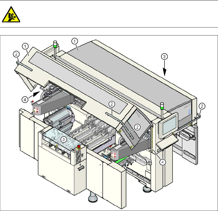
Fig. 2.5 - 1 Safety instructions for closing the protective covers
(1) Protective covers
(2) Grab handles
(3) Cover flaps over the PCB conveyor
(4) Warning strips