CP45松下驱动器部分.pdf - 第11页
9. Motor & Driver Ver. Date CP45 CP45NEO 00 2004/11 O O 9-2 9-2-5-1 Check Point for DRIVE Trouble -S y n o p s i s : *Error Sequence of Drive (Error Occurs->Dynamic Brak er/Motor On/Servo Output/ Alarm O n->Can…
9. Motor & Driver
Ver. Date CP45
CP45NEO
00 2004/11 O O
9-2
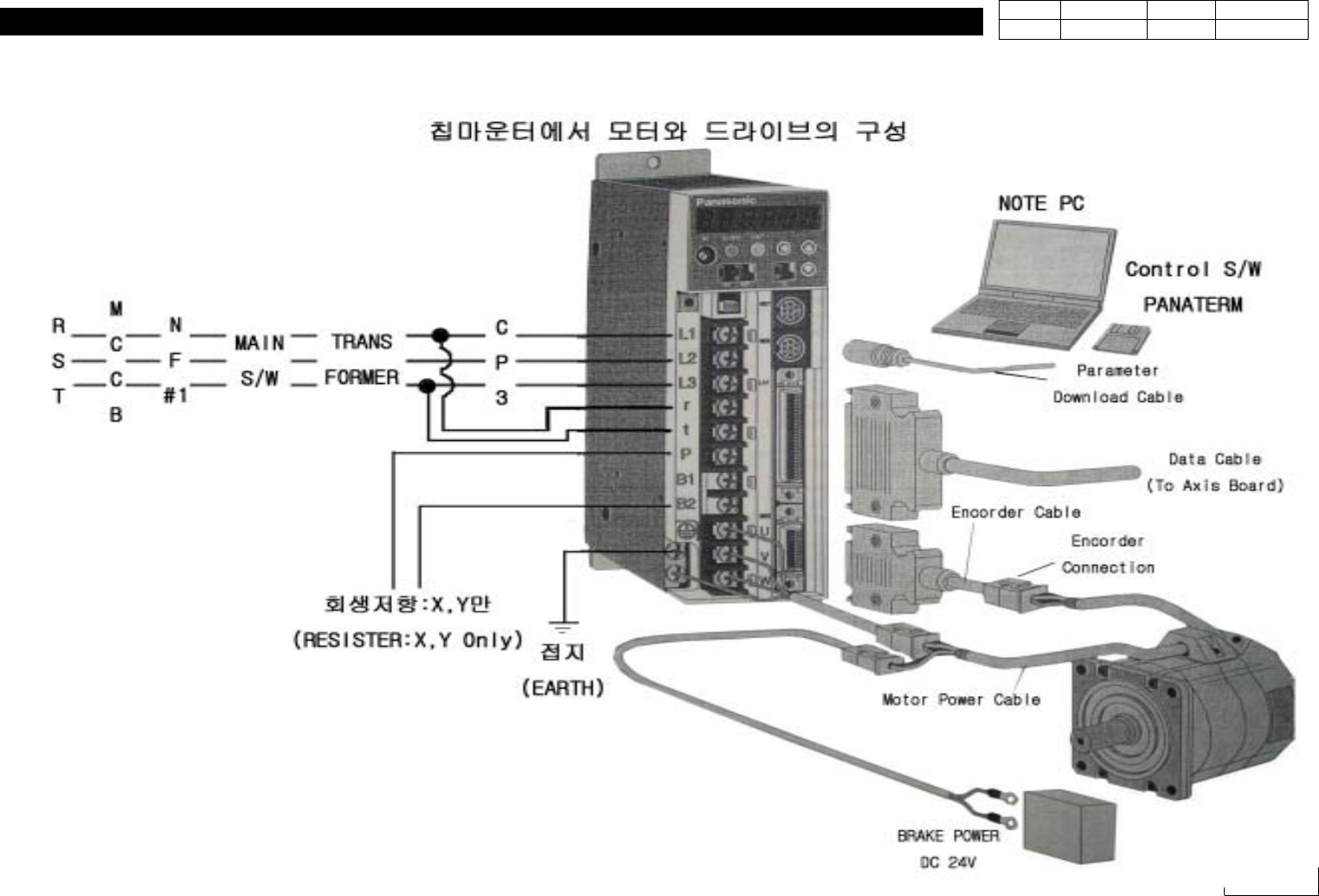
9-2-5. Construction of P-Motor Driver and Measures for Error
9. Motor & Driver
Ver. Date CP45
CP45NEO
00 2004/11 O O
9-2
9-2-5-1 Check Point for DRIVE Trouble
-Synopsis:
*Error Sequence of Drive
(Error Occurs->Dynamic Braker/Motor On/Servo Output/
Alarm On->Cancel Brake)
When this Sequence is Operated, Motor Stops and Alarm Sounds
9-2-5-2 Trouble Symptoms and Treatment(Refer Next "Appendix" Page for
Detailed Alarm)
-Alarm Code is Indicated on the LED of Front Panel when Trouble Occurs
-At this time Servo is OFF and A-CLR Should be done for more than 120ms to
Cancel it. But in the Equipment it can be done through EMG RESET or
STOP->RESET->READY. Power Should be OFF/ON for Alarm Related to
Power.
-For the Alarm by OVERLOAD Normal Clear is Possible after 10 Seconds, so
Wait for more than 10 Seconds and Approve READY POWER for this Alarm
-For the Trouble by the Connection Problem of Motor Terminal or Wiring Error,
be Sure to Turn Off All the Power to Check/Install Wiring
-When Motor is not Running, the Circuit in Drive is Damaged or Parameter is
not OK if There is no Kinematic Error. Replace.
-If the Rotation of Motor is Unstable and Acceleration/Decelaration is not
Smooth, it can be Caused by Kinematic Effect. But Check Shield of Cable as
There can be Wrong Parameter, Change of Main Power or the Noise of Cable
-If the Origin is Deviated, Check Contact of Axis Board as There can be Big
Difference btw. Z-phase and Home Sensor or the Error of Axis Board
-The Cause of Noise is Mainly Parameter, Disconnection of Cable Except
Kinematic Reason
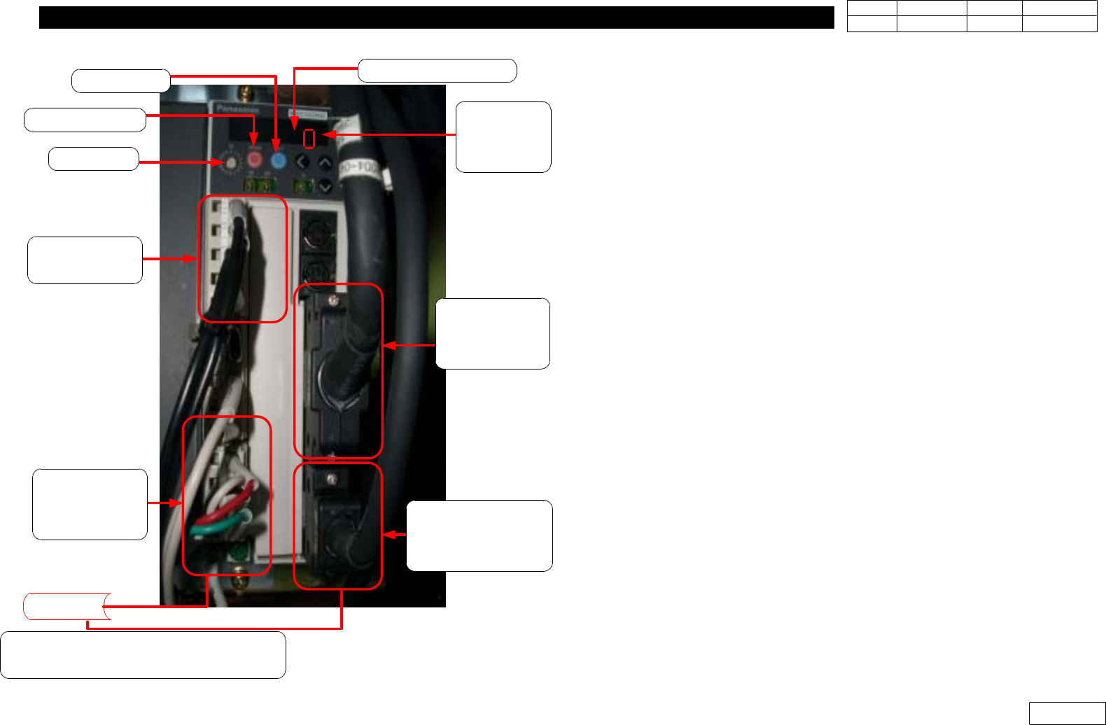
Alarm Code Check!
Parameta
Setting
Check!
Inteface Check!
(From Drive to
Axis Board)
Motor Encorder
Cable Connection/
Pin Check!
Input Power/
Pin Check!
Motor Power/
Pin Check!
Earth Check!
Motor
Motor Noise / Mechanical Trouble /
EMG Switch Check!
ID Switch
MODE Switch
SET Switch
9. Motor & Driver
Ver. Date CP45
CP45NEO
00 2004/11 O O
9-2
9-3 Parameter Load/Unload of SANYO Q-Type Motor Driver(=Amplifier)
9-3-1 Connection btw. Q-Motor Driver(=Amplifier) and Computer
* Tools
a) Notebook Computer
b) Cable for interface
1) Open Lower Cover of Rear Equipment
2) Prepare Laptop Installed with Q-SETUP Software
3) Prepare Exclusive Interface Cable as Fig.9-3-1-1 and Connect it to Laptop(RS232 Port)
4) W hen Connecting Interface Cable, Temporarily Block the Power Diverged to Driver from
Chip Mounter to Prevent the Damage of Driver(=Amplifier)(CP#2 Off :Fig 9-3-1-2)
5) Connect Interface Cable to the Port of Applying Amplifier as Fig.9-3-1-2
6) After Connecting Cable, Turn CP#2 On to Approve the Power to Driver
9-3-2. Software Run and Connection with Amplifier
1) Run Q-SETUP Software of Laptop
2) When Q-SETUP Software is Run, Window as Fig 9-3-2-1 Appears
3) Running Icon Connecting On-line Displays the Window of Communication State as Fig
9-3-2-2. Press 'Check' Button to Check Connection State.
4) When the error massage
"not corresponding"
is displated,
=> Please revise the latest version of 'Q-Setup' program
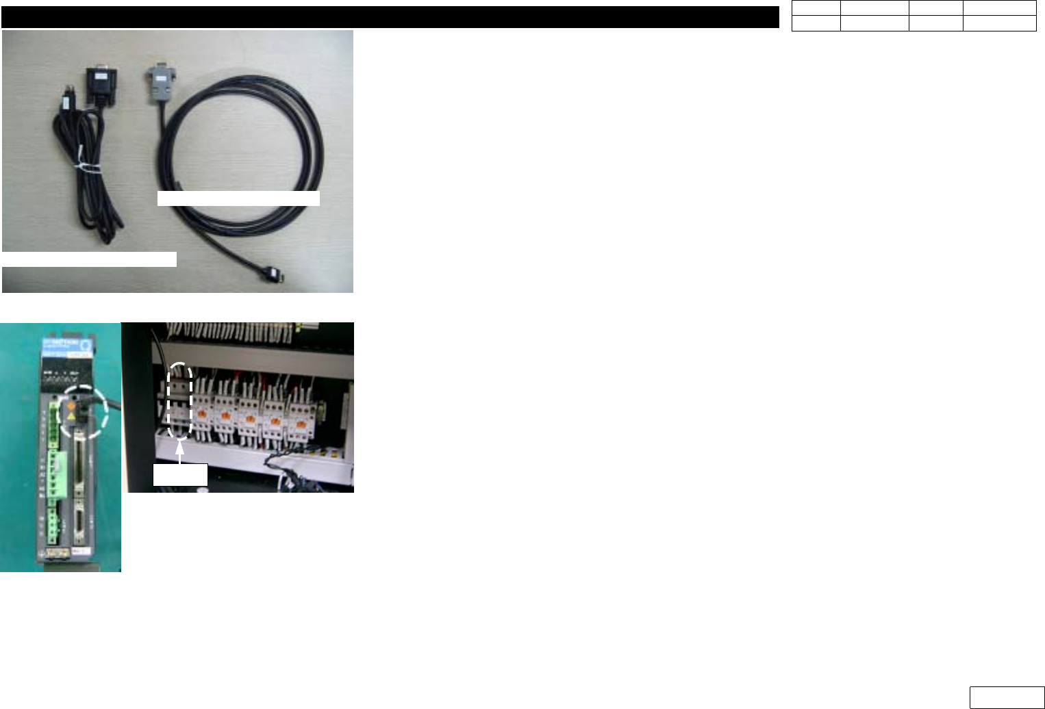
Fig.9-3-1-1 Interface Cable for Pana. Amplifier
Cable for Panasonic
Cable for Q-series
Fig.9-3-1-2 Connect I/F cable to Amplifier /
CP#2 off for safety
CP#2