00193922-03.pdf - 第111页
User manual SIPLAC E HF series 3 Technical data Software Vers ion SR.50x.xx 01/2006 US Edition 3.4 Dimensions and weight of the placement m achines 111 3.4.12 Maneuvering di stance for the matrix tray changer 3 3 3 3 Fig…
3 Technical data User manual SIPLACE HF series
3.4 Dimensions and weight of the placement machines Software Version SR.50x.xx 01/2006 US Edition
110
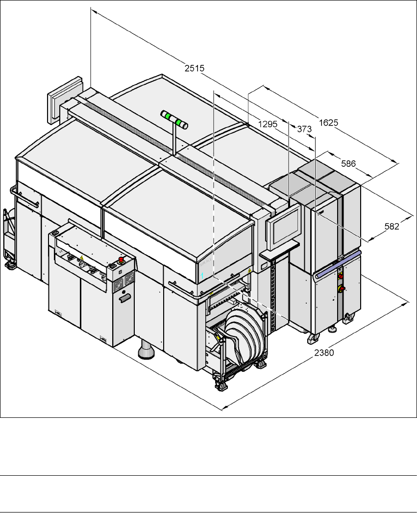
3.4.11 Dimensions of the HF/3 placement system with matrix tray changer
3
3
3
3
Fig. 3.4 - 11 Dimensions of the HF /3 placement system with matrix tray changer in millimeters
3
3
PLEASE NOTE 3
The matrix tray changer can only be docked in at location 2.
3
User manual SIPLACE HF series 3 Technical data
Software Version SR.50x.xx 01/2006 US Edition 3.4 Dimensions and weight of the placement machines
111
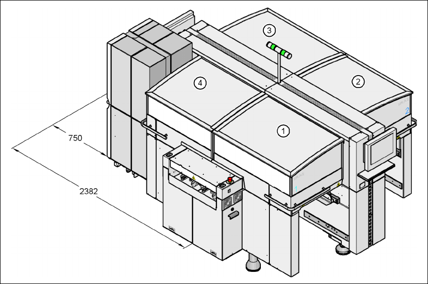
3.4.12 Maneuvering distance for the matrix tray changer
3
3
3
3
Fig. 3.4 - 12 Maneuvering distance for the MTC
1, 2, 3, 4 Locations no. 1, 2, 3, 4 3
HF machine: Locations 2 and 4 3
HF/3 machine: Location 2 only 3
3
3 Technical data User manual SIPLACE HF series
3.5 Line concept Software Version SR.50x.xx 01/2006 US Edition
112
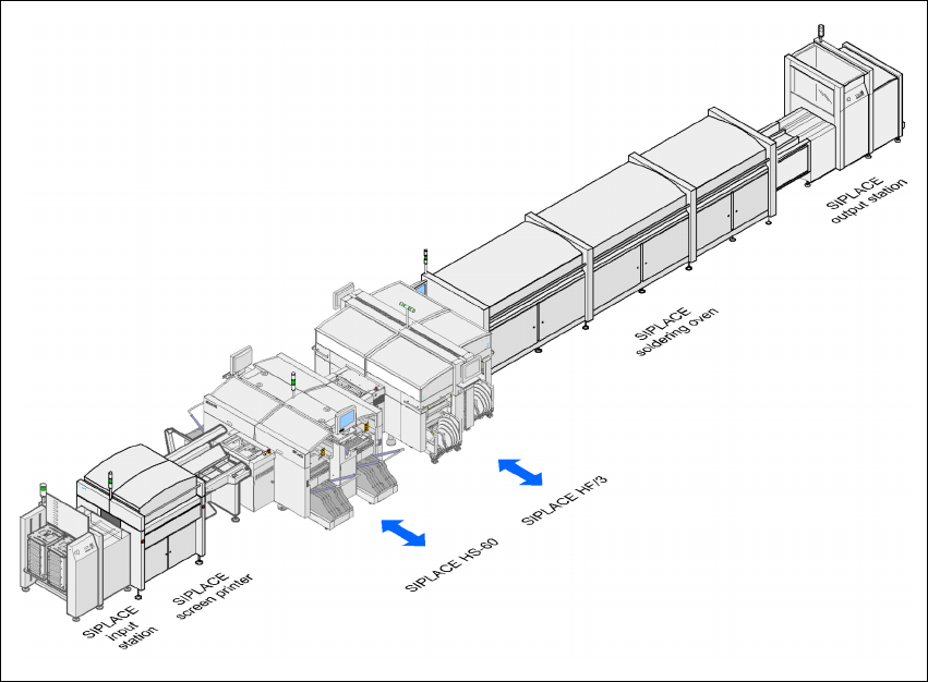
3.5 Line concept
3.5.1 Description
The SIPLACE concept is characterized by its flexibility, modularity, compactness and high power
density. It allows a production line to be individually configured from identical and different mod-
ules. If the production requirements change, the individual placement machines are so compact
that they can be recombined quickly and easily. 3
3
Fig. 3.5 - 1 Sample line concept
3
The SIPLACE family has exactly the right placement machine, whatever the output require-
ments: 3
SIPLACE HF and HF/3 placement machines can be used to place IC, flip-chip, bare die and
exotic components (OSC). They cover the spectrum of components from 0201 to 85 x 85 / 125
x 10 mm² with a high placement rate. 3
The SIPLACE HS-60 is a super high-speed placement machine for processing components
ranging from 0201 through to 18.7 x 18.7 mm². 3