00193922-03.pdf - 第124页
3 Technical data User manual SIPLACE HF series 3.7 Placement heads S oftware Version SR.50x.x x 01/2006 US Edition 124 3 Fig. 3.7 - 7 6-segment Collect&Place head - Function groups, part 2 3 (1) Intermed iate dist ri…
User manual SIPLACE HF series 3 Technical data
Software Version SR.50x.xx 01/2006 US Edition 3.7 Placement heads
123
3.7.3 6-segment Collect&Place head for high-speed IC placement
3
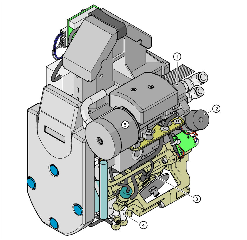
Fig. 3.7 - 6 6-segment Collect&Place head - Function groups, part 1
3
(1) Vacuum generator
(2) Turning station, DP axis
(3) Star with 6 sleeves - star axis
(4) Forced air valve
(5) Silencer
3 Technical data User manual SIPLACE HF series
3.7 Placement heads Software Version SR.50x.xx 01/2006 US Edition
124
3
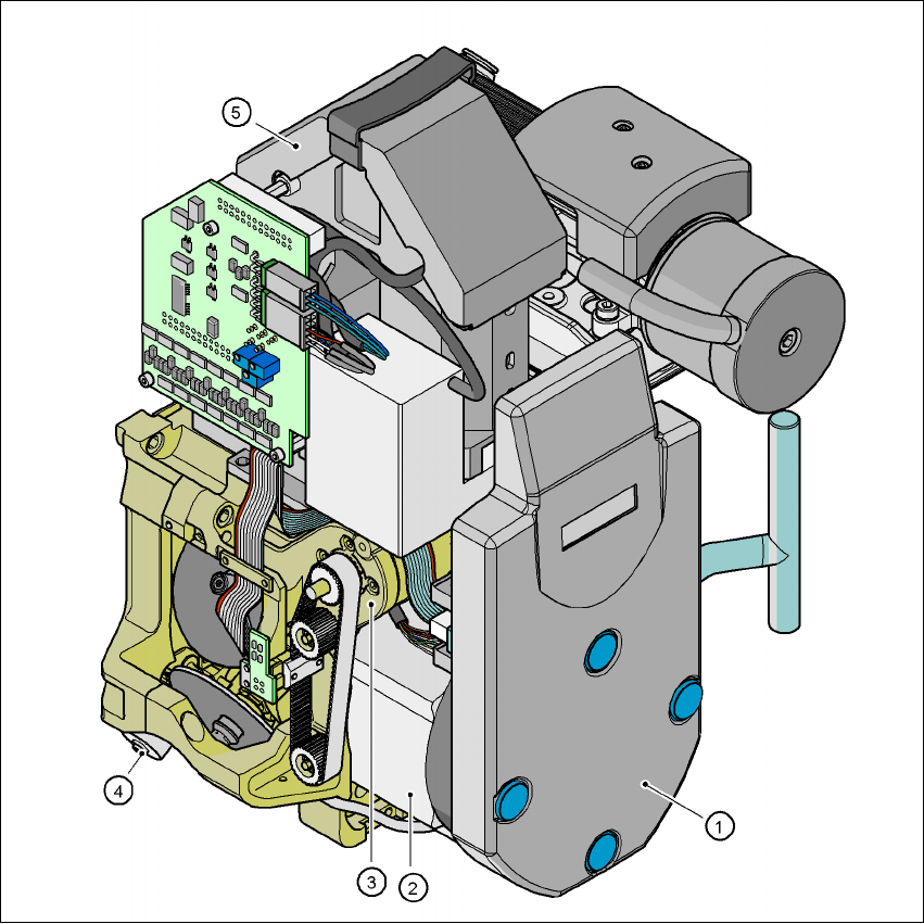
Fig. 3.7 - 7 6-segment Collect&Place head - Function groups, part 2
3
(1) Intermediate distributor board, beneath the cover
(2) Star drive - DR motor
(3) Z axis motor
(4) Valve adjustment drive
(5) 39 x 39 component vision camera
User manual SIPLACE HF series 3 Technical data
Software Version SR.50x.xx 01/2006 US Edition 3.7 Placement heads
125
3.7.3.1 Description
The 6-segment Collect&Place head also works on the Collect&Place principle. With the stan-
dard component vision module, the HF machine places components with an edge length of up
to 32 mm quickly and very accurately. It is therefore ideal for use with products containing a large
proportion of ICs. A considerable increase in output can be achieved even in the main application
range from PLCC 44 to QFP 208. 3
The 6-segment Collect&Place head can optically center and place components from 0.6 x
0.3 mm² to 13 x 13 mm² using the optional DCA vision module. The DCA vision module optimizes
the speed and accuracy when placing high-speed flip-chips and bare die components The values
are shown in the table on page 127
. 3
Checking and self-learning functions 3
The checking and self-learning functions described on page 120 for the 12-segment
Collect&Place head also apply to the 6-segment Collect&Place head. 3
3.7.3.2 Description of the functions
3
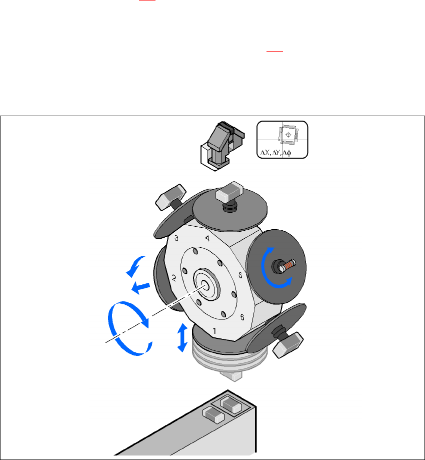
Fig. 3.7 - 8 Description of the functions
Component camera
DP axis
Rotate component
into placement position
Remove sleeve
or insert
Z axis
Pick up component
or place it
Star axis
Star rotation
Reject component