00193922-03.pdf - 第129页
User manual SIPLAC E HF series 3 Technical data Software Vers ion SR.50x.xx 01/2006 US Edition 3.7 Placement heads 129 3.7.4.1 Descriptio n This sop histic ated placeme nt hea d consists o f two plac ement hea ds of the …
3 Technical data User manual SIPLACE HF series
3.7 Placement heads Software Version SR.50x.xx 01/2006 US Edition
128
3.7.4 SIPLACE TwinHead for high-precision IC placement
3
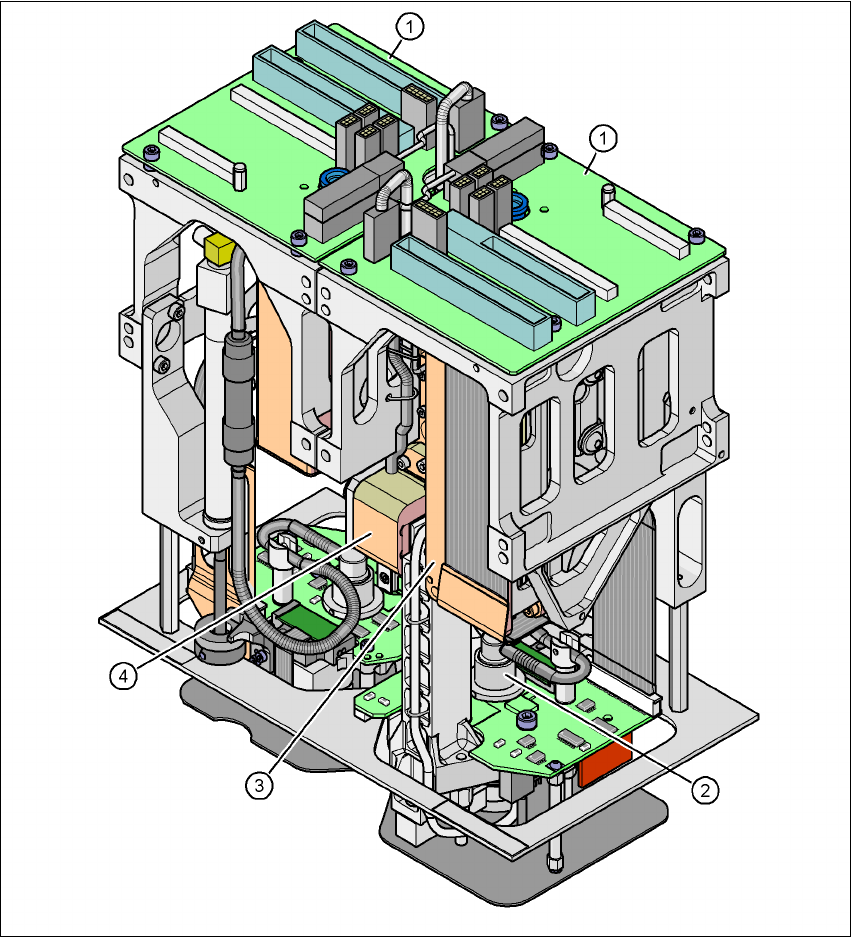
Fig. 3.7 - 9 TwinHead for high-precision IC placement
3
(1) Pick&Place module - the TwinHead consists of 2 Pick&Place modules
(2) DP axis
(3) Z axis drive
(4) Incremental distance measuring system for the Z axis

User manual SIPLACE HF series 3 Technical data
Software Version SR.50x.xx 01/2006 US Edition 3.7 Placement heads
129
3.7.4.1 Description
This sophisticated placement head consists of two placement heads of the same type coupled to-
gether (twin head). Both heads work using the Pick&Place principle. The TwinHead is suitable for
processing particularly difficult or large components. Two components are picked up by the place-
ment head, optically centered on the way to the placement position and rotated into the necessary
placement angle. They are then placed gently and accurately onto the PCB with a controlled blast
of air. 3
New nozzles (type 5xx) have been developed for the TwinHead. It is also possible to fit an adapter
and then use type 4 nozzles for the Pick&Place head and type 8xx and 9xx nozzles for the Col-
lect&Place heads. 3
Checking and self-learning functions 3
The TwinHead's reliability can be further increased with various checking and self-learning func-
tions. 3
– For example, vacuum checks at the nozzles indicate whether the component was picked up
or set down correctly.
– High-resolution, intelligent vision modules, such as the fine-pitch and flip-chip vision modules,
identify and correct minute deviations from the desired component position, thus guarantee-
ing a correct placement position. The component cameras are permanently fixed to the ma-
chine frame.
– The component package form is also checked, and the component is not placed if the geo-
metric data thus determined differs from the programmed data.
– A force sensor measures and monitors the specified component placement forces.
– If the compressed air or power fails, the vertical axis (Z axis) is raised to a safe position in
order to prevent a head crash.
3.7.4.2 Description of the functions
The TwinHead consists of two Pick&Place heads that are coupled to one another, but are con-
trolled independently. Each head has two axes - the Z and the DP axis (see Fig. 3.7 - 8
). 3
The traversing path of the Z axis is detected via a high-resolution, linear incremental measuring
system. The Z axis performs a vertical movement. A linear motor raises and lowers the Z axis,
and components are picked up from feeder modules or trays and lowered onto the PCB. The
Z axis is an "intelligent axis". It "notes" the pick-up height for feeder modules and trays and the
placement height for each component. This can speed up the placement process. The pro-
grammed placement force is measured and monitored by a force sensor. 3
3 Technical data User manual SIPLACE HF series
3.7 Placement heads Software Version SR.50x.xx 01/2006 US Edition
130
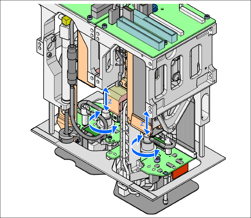
The DP axis rotates the optically centered component to the desired placement angle. The ro-
tation axis is driven by a stepping motor. The motor shaft is designed as a sleeve. At the top end
is the incremental disk for angle analysis, while the nozzle holding device is at the bottom end. 3
The sequences of movements of the rotation and translation axes are controlled by control cir-
cuits. Position and speed sensors send the actual values for the axis movement to the axis con-
trol. The setpoint and actual values are compared and used to determine the force and speed
parameters for the servo amplifier, and thus the axis movement to be performed. 3
The vacuum values at the nozzle are constantly checked throughout the entire pick-up and
placement process in order to keep the placement error rate as low as possible. 3
3
Fig. 3.7 - 10 Description of the functions
3