00193922-03.pdf - 第149页
User manual SIPLAC E HF series 3 Technical data Software Vers ion SR.50x.xx 01/2006 US Edition 3.11 V ision modules 149 3.1 1.4 PC B vision c amera, standard (ty pe 5) 3.1 1.4. 1 Position 3 Fig. 3.1 1 - 5 PCB vision came…
3 Technical data User manual SIPLACE HF series
3.11 Vision modules Software Version SR.50x.xx 01/2006 US Edition
148
3.11.3 Component vision camera for the TwinHead
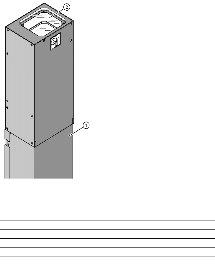
3.11.3.1 Structure of the component vision camera (stationary, P&P (type 22) 50 x 40)
3
Fig. 3.11 - 4 Structure of the component vision camera (stationary, P&P (type 22) 50 x 40)
3.11.3.2 Technical data
3
(1) Camera housing with integral camera and
camera amplifier
(2) Glass plate - over the illumination and lens
levels
Component dimensions Up to 50 x 40 mm² for a single component measurement
Range of components 0603, MELF, SO, PLCC, QFP, electrolytic capacitors, BGA
Min. lead pitch 0.4 mm
Min. ball/bump diameter 0.32 mm
Field of vision 60 x 45 mm²
Method of illumination Front-lighting (6 levels, programable as required)
User manual SIPLACE HF series 3 Technical data
Software Version SR.50x.xx 01/2006 US Edition 3.11 Vision modules
149
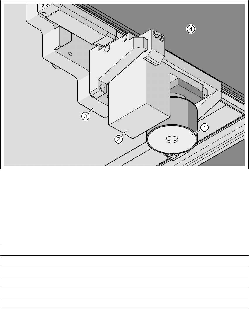
3.11.4 PCB vision camera, standard (type 5)
3.11.4.1 Position
3
Fig. 3.11 - 5 PCB vision camera, standard (type 5) on the gantry - view from below
(1) PCB camera lens and illumination
(2) Camera amplifier
(3) Head mount
(4) Gantry
3.11.4.2 Technical data
PCB fiducials Up to 3 (subpanels and multiple panels)
Local fiducials Up to 2 per PCB (may be of different types)
Library size Up to 255 fiducial types - system fiducials ≥ 249
Image processing Geometric alignment
Method of illumination Front-lighting
Detection time per fiducial/bad fiducial 0.4 s
Field of vision 5.7 x 5.7 mm²
3 Technical data User manual SIPLACE HF series
3.12 PCB single conveyor Software Version SR.50x.xx 01/2006 US Edition
150
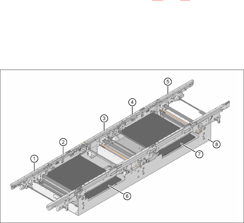
3.12 PCB single conveyor
The placement machine is supplied with a single PCB conveyor as standard. The dual PCB con-
veyor is available as an option from the factory (see Section 3.13
, page 153). The left or the right
side of the PCB conveyor can be used as the stationary side, as required. 3
The conveyor belts are driven by DC motors. There is a lifting table for clamping the PCBs in
each processing area. The PCB conveyor width can either be set from the user interface or pre-
set in the placement program. 3
3.12.1 Structure
3
Fig. 3.12 - 1 Structure of the PCB single conveyor
(1) Input conveyor
(2) Processing conveyor 1
(3) Intermediate conveyor
(4) Processing conveyor 2
(5) Output conveyor
(6) Lifting table 1
(7) Lifting table 2
(8) Assembly trough