00193922-03.pdf - 第154页
3 Technical data User manual SIPLACE HF series 3.13 Flexible dual PCB conveyor Software Vers ion SR.50x.xx 01/2006 US E dition 154 3.13. 2 T echnical dat a 3 Fixe d conv eyor side Ri ght or le ft PCB form at Standa rd (l…
User manual SIPLACE HF series 3 Technical data
Software Version SR.50x.xx 01/2006 US Edition 3.13 Flexible dual PCB conveyor
153
3.13 Flexible dual PCB conveyor
3.13.1 Structure
3
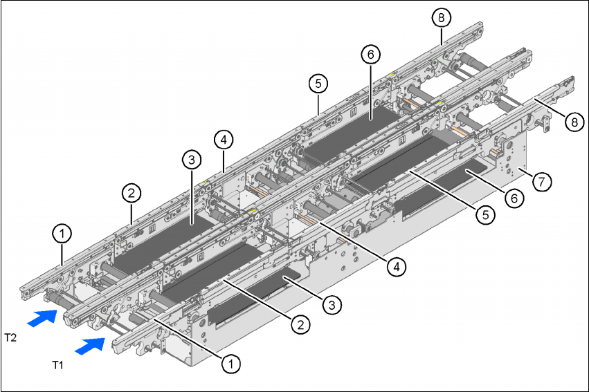
Fig. 3.13 - 1 Structure of the PCB dual conveyor
(1) Input conveyor
(2) Processing conveyor 1
(3) Lifting table 1
(4) Intermediate conveyor
(5) Processing conveyor 2
(6) Lifting table 2
(7) Assembly trough
(8) Output conveyor
T1 Conveyor track 1
T2 Conveyor track 2

3 Technical data User manual SIPLACE HF series
3.13 Flexible dual PCB conveyor Software Version SR.50x.xx 01/2006 US Edition
154
3.13.2 Technical data
3
Fixed conveyor side Right or left
PCB format
Standard (length x width)
"Wide board" configuration
Long board option
Long board option and "Wide board"
configuration
Dual conveyor in "Single conveyor" mode
Standard (length x width)
"Wide board" configuration
Long board option
Long board option and "Wide board"
configuration
50 x 50 mm² to 450 x 216 mm² (item no. 00119627-xx)
50 x 50 mm² to 450 x 250 mm² (item no. 00119629-xx)
50 x 80 mm² to 610 x 216 mm² (item no. 00119672-xx)
50 x 80 mm² to 610 x 250 mm²
50 x 50 mm² to 450 x 380 mm²
50 x 50 mm² to 450 x 450 mm²
50 x 80 mm² to 610 x 380 mm²
50 x 80 mm² to 610 x 450 mm²
PCB thickness
Standard 0.3 mm to 4.5 mm ± 0.2 mm
(thicker PCBs available on request)
Max. PCB warpage Up: 6 mm - PCB thickness
Down: 0.3 mm + PCB thickness
PCB weight Max. 3 kg
Clearance on PCB underside
Standard
Option
25 mm ± 0.2 mm
Max. 40 mm ± 0.2 mm
PCB transport height 830mm ± 15mm (standard)
900mm ± 15mm (optional)
930mm ± 15mm (optional)
950mm ± 15mm (SMEMA: optional)
Type of interface SMEMA / SIEMENS
Component-free PCB handling edge 3 mm
PCB changeover time < 2.5 s
PCB positioning accuracy ± 0.5 mm
Conveyor mode Synchronous or asynchronous
Components on each conveyor Same or different
PCB width on each conveyor Same or different
Bad fiducial detection Synchronous: impossible, asynchronous: possible
Automatic width adjustment Synchronous: possible, asynchronous: possible
User manual SIPLACE HF series 3 Technical data
Software Version SR.50x.xx 01/2006 US Edition 3.13 Flexible dual PCB conveyor
155
3.13.3 Description of the functions
The flexible dual conveyor has two conveyor tracks that are electrically and mechanically inde-
pendent of one another. The functions are the same as for the single conveyor (see Section
3.12.3
, page 151. 3
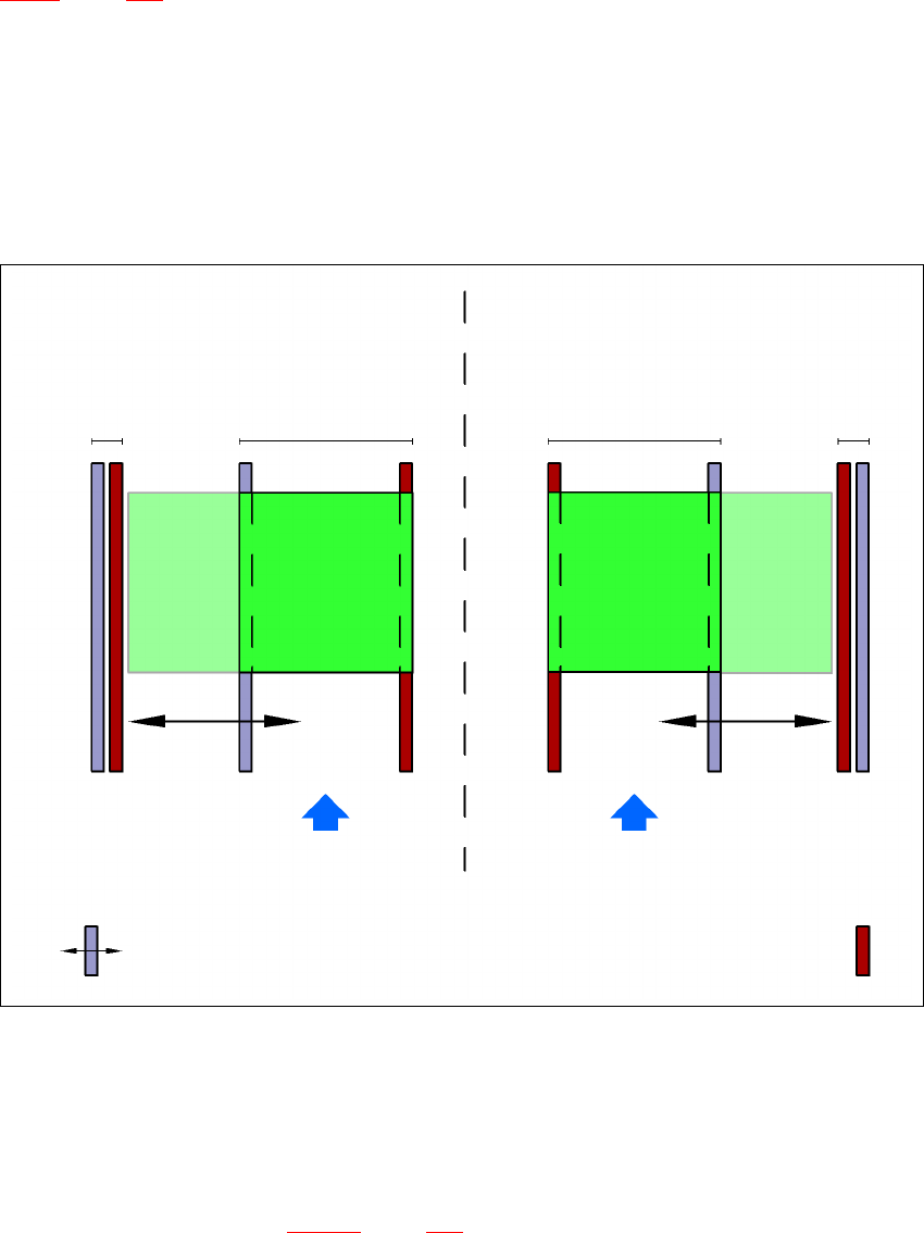
3.13.4 "Flexible dual conveyor" performance feature
The "flexible dual conveyor" performance feature allows the conveyor track to be widened be-
yond the standard width of 216 mm. Over-wide PCBs can then be processed in a machine with
a dual conveyor. The side walls of the second conveyor track are moved fully together, which
deactivates the conveyor track at the same time. 3
3
Fig. 3.13 - 2 Flexible dual conveyor in Single conveyor mode
3
3
3.13.5 Defining the conveyor tracks
The right conveyor track (viewed in the transport direction) is designated "Conveyor 1" and the
left as "Conveyor 2" (see Fig. 3.13 - 3
, page 156). 3
Dual conveyor with widened conveyor track 2
(stationary conveyor side wall on left)
Conveyor track 2
deactivated
Conveyor track 1 Conveyor track 2 Conveyor track 1
deactivated
PCB transport direction PCB transport direction
Stationary conveyor side wall
Dual conveyor with widened conveyor track 1
(stationary conveyor side wall on right)
Movable conveyor side wall