00193922-03.pdf - 第203页
User manual SIPLAC E HF series 4 Setting up and commissioning Software Vers ion SR.50x.xx 01/2006 US Edition 4.4 Setting up the placement machine 203 4 Fig. 4.4 - 16 Fitting the conveyor cover and t he second half of the…
4 Setting up and commissioning User manual SIPLACE HF series
4.4 Setting up the placement machine Software Version SR.50x.xx 01/2006 US Edition
202
Æ Remove both side plates (item 6 in Fig. 4.4 - 15).
CAUTION 4
Do not unscrew the three bottom screws straight away. Simply loosen them so that the side
plate does not fall off.
Æ Detach the ground cable from the side plate.
Æ Remove both doors (item 2 in Fig. 4.4 - 15) from the extension kit (item 1).
PLEASE NOTE: 4
To avoid damage, we recommend that a second person helps to assemble the extension kit.
Æ Set down the computer unit (item 8 in Fig. 4.4 - 15) and the axis unit (item 9 in Fig 4.4 - 15)
at the side of the machine in order to make enough space to fit the extension kit (item 1 in Fig.
4.4 - 15
).
Æ Make sure that the connecting cables to the computer and axis units are not too tight.
Æ Lift one half of the extension kit (item 1 in Fig. 4.4 - 15) against the machine frame and position
it so that the assembly bracket lies on the assembly bar (item 7 in Fig. 4.4 - 15
).
CAUTION 4
Make sure that the extension kit does not collide with the hexagonal shaft of the PCB con-
veyor and thus become bent.
Æ Fix this half of the extension kit using 2 fillister head screws M6x16 and washers (item 3 in
Fig. 4.4 - 15
).
Æ
Before
assembling the second half of the extension kit, fit the conveyor cover (item 5 in Fig.
4.4 - 15
). The procedure is as follows:
User manual SIPLACE HF series 4 Setting up and commissioning
Software Version SR.50x.xx 01/2006 US Edition 4.4 Setting up the placement machine
203
4
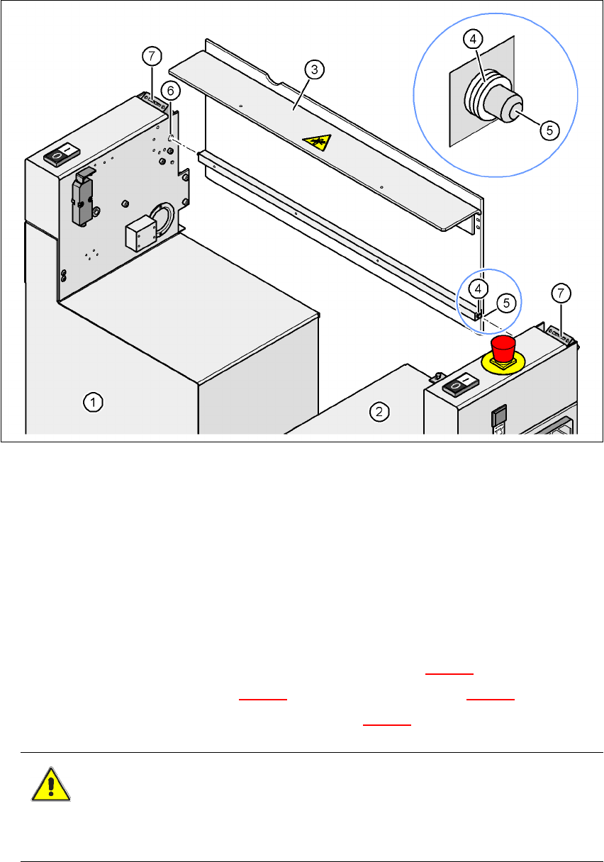
Fig. 4.4 - 16 Fitting the conveyor cover and the second half of the extension kit
(1) Half of the extension kit already fitted
(2) Second half of the extension kit to be fitted
(3) Conveyor cover
(4) Insert 3 white plastic washers on both sides
(5) Mandrel of the conveyor cover
(6) Hole
(7) Protective cover switch
4
Æ Push 3 white plastic washers onto each mandrel (item 5 in Fig. 4.4 - 16).
Æ Guide the mandrel (item 5 in Fig. 4.4 - 16) into the hole (item 6 in Fig. 4.4 - 16).
Æ Lift the second half of the extension kit (item 2 in Fig. 4.4 - 16) against the machine frame.
CAUTION 4
Make sure that this half of the extension kit does not collide with the hexagonal shaft of the
PCB conveyor and thus bend the shaft.

4 Setting up and commissioning User manual SIPLACE HF series
4.4 Setting up the placement machine Software Version SR.50x.xx 01/2006 US Edition
204
Æ Introduce the mandrel (item 5 in Fig. 4.4 - 16) of the conveyor cover into the hole (item 6 in
Fig. 4.4 - 16
) in the second half of the extension kit.
Æ Position the second half of the extension kit so that the assembly bracket lies on the assembly
bar (item 7 in Fig. 4.4 - 15
).
Æ Fix the second half of the machine using 2 fillister head screws M6x16 and washers (item 3
in Fig. 4.4 - 15
).
4.4.10.3 Fixing the hexagonal shaft guide
Æ On the single conveyor, fix
one
guide for the hexagonal shaft (item 8 in Fig. 4.4 - 14) to the
extension kit using two fillister head screws M6x16 and washers.
Æ On the double conveyor, fix two guides for the hexagonal shaft (item 8 in Fig. 4.4 - 14) to the
extension kit using two fillister head screws M6x16 and washers.
4.4.10.4 Connecting the power cables - Extension kit on the PCB input side
4
4
Left-hand side of the extension kit
(viewed in the direction of travel)
Connector/cable To connector/cable
Start/Stop button
Switch, PCB conveyor cover
X61/03020410 X61/03002537
Protective cover switch, location 4 X54/03020409 X54/03002540
Button for the component trolley docking unit,
location 4
X242/03021056 X242/03021054
Right-hand side of the extension kit
(viewed in the direction of travel)
Connector/cable To connector/cable
Emergency stop button
Start/Stop button
X64/03020687 X64/03002538
Protective cover switch, location 1 X51/03020409 X51/03002539
Button for the component trolley docking unit,
location 1
X212/03021056 X212/03021051