00193922-03.pdf - 第223页
User manual SIPLAC E HF series 4 Setting up and commissioning Software Vers ion SR.50x.xx 01/2006 US Edition 4.5 Adapting t he component trolley to the PCB transport height 223 4.5.1 W arning instructions W ARNING Only S…
4 Setting up and commissioning User manual SIPLACE HF series
4.5 Adapting the component trolley to the PCB transport height Software Version SR.50x.xx 01/2006 US Edition
222
4.5 Adapting the component trolley to the PCB trans-
port height
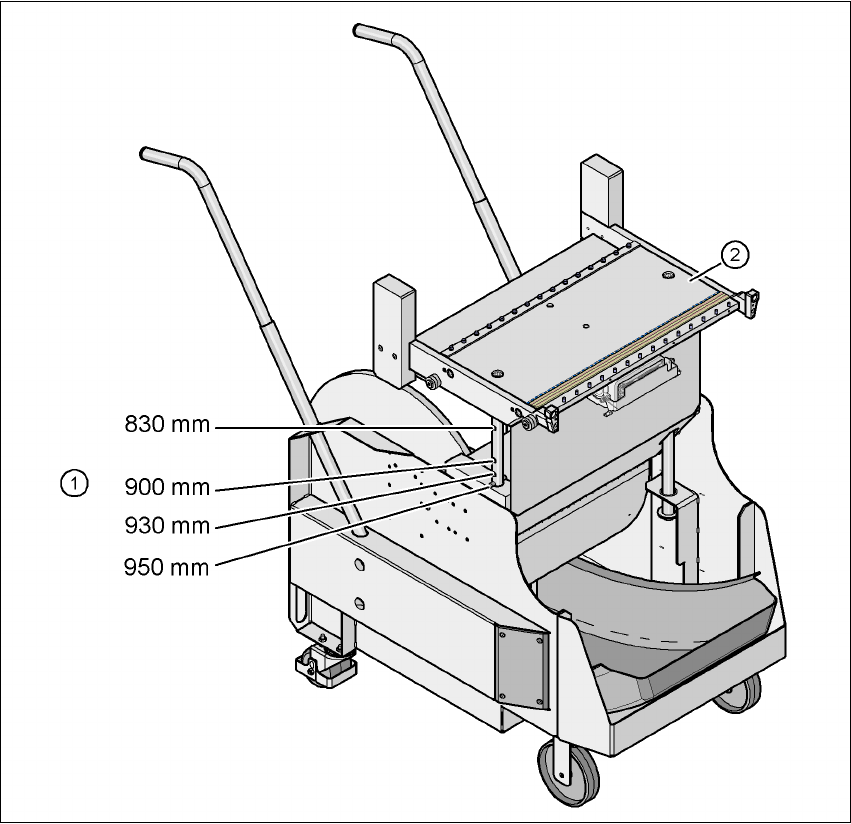
The component trolley can be set to the following PCB transport heights with just a few simple
actions:
830 mm ± 15 mm Standard height
900 mm ± 15 mm SMEMA height
930 mm ± 15 mm SMEMA height
950 mm ± 15 mm SMEMA height 4
4
Fig. 4.5 - 1 Component trolley with a PCB transport height of 950 mm
(1) Holes in the guide columns for the transport heights of 830 to 950 mm
(2) Component trolley table
User manual SIPLACE HF series 4 Setting up and commissioning
Software Version SR.50x.xx 01/2006 US Edition 4.5 Adapting the component trolley to the PCB transport height
223
4.5.1 Warning instructions
WARNING
Only Siemens engineers or qualified personnel are permitted to adjust the component trolley
height.
Æ Always follow the applicable accident prevention regulations.
Æ Remove all the feeder modules from the component table bed if you want to adjust the height
of the component feeder table.
4.5.2 Tools and equipment
You will need the following tools and equipment to adjust the height of the component trolley:
– Hammer
– Punch, 8 mm
– Eye-bolt with M12 thread for raising the component trolley table
– Lifting device for raising the component trolley table, carrying capacity at least 80 kg
4.5.3 Changing the component trolley height
WARNING
Remove all the feeder modules from the component trolley table bed.
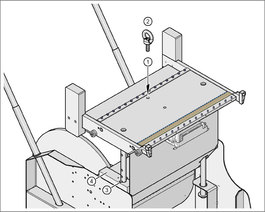
Æ Screw the eye-bolt into the M12 hole (item 1 in Fig. 4.5 - 2) in the component trolley table bed.
Æ Attach the hooks of the lifting device to the eye-bolt (item 2 in Fig. 4.5 - 2).
Æ Raise the component trolley bed slightly to expose the split pins (item 3 in Fig. 4.5 - 2).
Æ Use the punch to carefully tap out the spiral pins on both sides.
Æ Insert the spiral clamping pins into the holes for the required PCB conveyor height (item 3 in
Fig. 4.5 - 2
).
Æ Lower the component trolley bed slowly until the split pins lie on the supporting blocks (item 4
in Fig. 4.5 - 2
).
4 Setting up and commissioning User manual SIPLACE HF series
4.5 Adapting the component trolley to the PCB transport height Software Version SR.50x.xx 01/2006 US Edition
224
Æ Unscrew the eye-bolt from the component trolley table.
4
Fig. 4.5 - 2 Positions of the eye-bolt and flange bolts
(1) M12 hole for eye-bolt
(2) Eye-bolt, DIN 580 M12-St
(3) Spiral clamping pin, DIN 7343, 8x40 - St, 2x
(4) Supporting block, 2x