00193922-03.pdf - 第270页
6 Component handling User ma nual SIPLACE HF series 6.2 Technical dat a for the S feeder modules S oftware Version S R.50x.xx 01/2006 US Edition 270 The amount of flux requ ired for th e process is reduced to a minimum c…
User manual SIPLACE HF series 6 Component handling
Software Version SR.50x.xx 01/2006 US Edition 6.2 Technical data for the S feeder modules
269
6.2.18.2 Changing the retainer
Æ Hold the retainer (G in Fig. 6.2 - 18) firmly. Press the thrust pad downwards (F in Fig. 6.2 - 18)
and remove the retainer by pressing it out sideways.
6.2.18.3 Data entry
Define the waffle-pack trays as described in the SIPLACE Pro operating instructions.
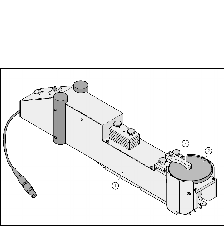
6.2.19 Dip module
6
Fig. 6.2 - 19 Dip module
(1) Dip module
(2) Rotating plate
(3) Squeegee
6.2.19.1 Principle of dip fluxing
The dip module (item 1) is used to wet flip-chip and CSP components with flux or conductive ad-
hesive. The flux holder is a rotating plate (item 2) on which a thin film of flux (e.g. 40 µm) is created
with a squeegee (item 3). This method is particularly suitable for highly viscous (honey-like) fluxes.
6 Component handling User manual SIPLACE HF series
6.2 Technical data for the S feeder modules Software Version SR.50x.xx 01/2006 US Edition
270
The amount of flux required for the process is reduced to a minimum coating thickness since only
the undersides of the bumps have to be wetted.
The dip module is suitable for all placement heads. It is regarded as a standalone type of conveyor
by the set-up optimization. There is no limit to the number of dip modules at the individual loca-
tions.
6.2.19.2 Technical data
Item no. 00117010-xx 6
Assigned locations 3 6
Component size Max. 36 x 36 mm²
depending on the placement head type 6
Possible coating thicknesses 25, 35, 45, 55, 65, 75 µm 6
Time required to change the coating thickness Less than 1 min. 6
Gap height tolerance ± 5 mm 6
Plate rotating speed Programmable from 0 - 10 sec.
in 0.1 sec. increments 6
Component dip time Programmable from 0 - 2 sec.
in 0.1 sec. increments 6
Flux Highly viscous flux, conductive adhesive 6
6
User manual SIPLACE HF series 6 Component handling
Software Version SR.50x.xx 01/2006 US Edition 6.3 Component trolley
271
6.3 Component trolley
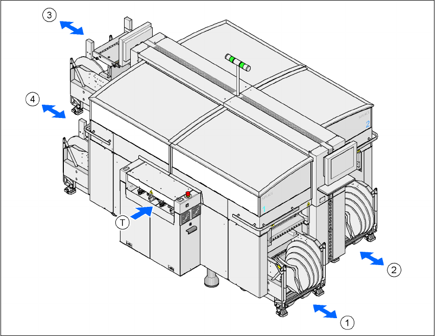
Up to four component trolleys may be docked to the SIPLACE HF series placement machine. The
locations are numbered as shown in the diagram below.
6
Fig. 6.3 - 1 Locations for the component trolleys
(1) Location 1
(2) Location 2
(3) Location 3
(4) Location 4
(T) PCB direction of travel
The component changeover tables are stand-alone modules that can be set up with feeders at an
external set-up area. This means that the production process only has to be interrupted briefly in
order to change the component trolley.