00193922-03.pdf - 第271页
User manual SIPLAC E HF series 6 Component handling Software Vers ion SR.50x.xx 01/2006 US Edition 6.3 Component trolley 271 6.3 Component tro lley Up to f our compon ent troll eys ma y be doc ked t o the SIP LACE HF ser…
6 Component handling User manual SIPLACE HF series
6.2 Technical data for the S feeder modules Software Version SR.50x.xx 01/2006 US Edition
270
The amount of flux required for the process is reduced to a minimum coating thickness since only
the undersides of the bumps have to be wetted.
The dip module is suitable for all placement heads. It is regarded as a standalone type of conveyor
by the set-up optimization. There is no limit to the number of dip modules at the individual loca-
tions.
6.2.19.2 Technical data
Item no. 00117010-xx 6
Assigned locations 3 6
Component size Max. 36 x 36 mm²
depending on the placement head type 6
Possible coating thicknesses 25, 35, 45, 55, 65, 75 µm 6
Time required to change the coating thickness Less than 1 min. 6
Gap height tolerance ± 5 mm 6
Plate rotating speed Programmable from 0 - 10 sec.
in 0.1 sec. increments 6
Component dip time Programmable from 0 - 2 sec.
in 0.1 sec. increments 6
Flux Highly viscous flux, conductive adhesive 6
6
User manual SIPLACE HF series 6 Component handling
Software Version SR.50x.xx 01/2006 US Edition 6.3 Component trolley
271
6.3 Component trolley
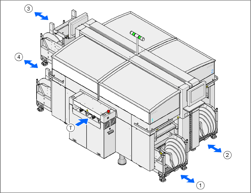
Up to four component trolleys may be docked to the SIPLACE HF series placement machine. The
locations are numbered as shown in the diagram below.
6
Fig. 6.3 - 1 Locations for the component trolleys
(1) Location 1
(2) Location 2
(3) Location 3
(4) Location 4
(T) PCB direction of travel
The component changeover tables are stand-alone modules that can be set up with feeders at an
external set-up area. This means that the production process only has to be interrupted briefly in
order to change the component trolley.
6 Component handling User manual SIPLACE HF series
6.3 Component trolley Software Version SR.50x.xx 01/2006 US Edition
272
PLEASE NOTE:
At external set-up positions, you will need an external power supply for the component trolley
(see section 6.3.5, page 278).
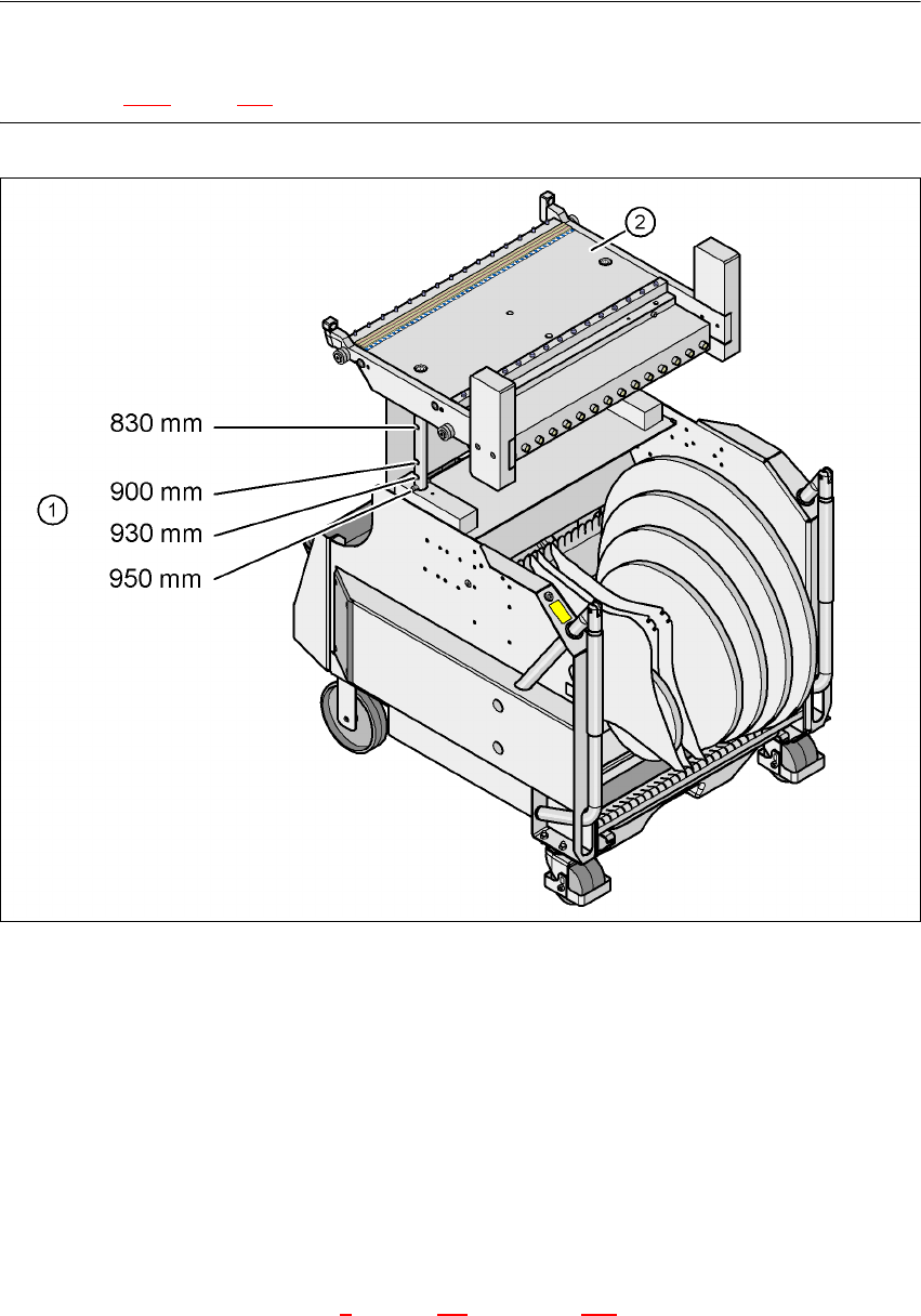
Fig. 6.3 - 2 Component trolley with a PCB transport height of 950 mm
6
(1) Holes in the guide columns for the transport heights of 830 to 950 mm
(2) Component trolley table
The design places considerable emphasis on ergonomics and safe operation.
– The trolleys move easily.
– No cables have to be plugged in to supply the component trolleys with power and com-
pressed air. The same applies to the communication interface.
– The component trolley is docked in/out the machine using a docking unit. A description of this
device can be found in chapter 5
, section 5.8, from page 240 onward. It is integrated into the
safety, supply and communication circuit or is disconnected from this circuit. Electronic prox-