00193922-03.pdf - 第313页
User manual SIPLAC E HF series 7 Station extensions Software Vers ion SR.50x.xx 01/2006 US Edition 7.1 Nozzle changer 313 7.1.3.3 Position of the nozzl e changers for the T w inHead on the HF/3 machine A nozzl e change r…
7 Station extensions User manual SIPLACE HF series
7.1 Nozzle changer Software Version SR.50x.xx 01/2006 US Edition
312
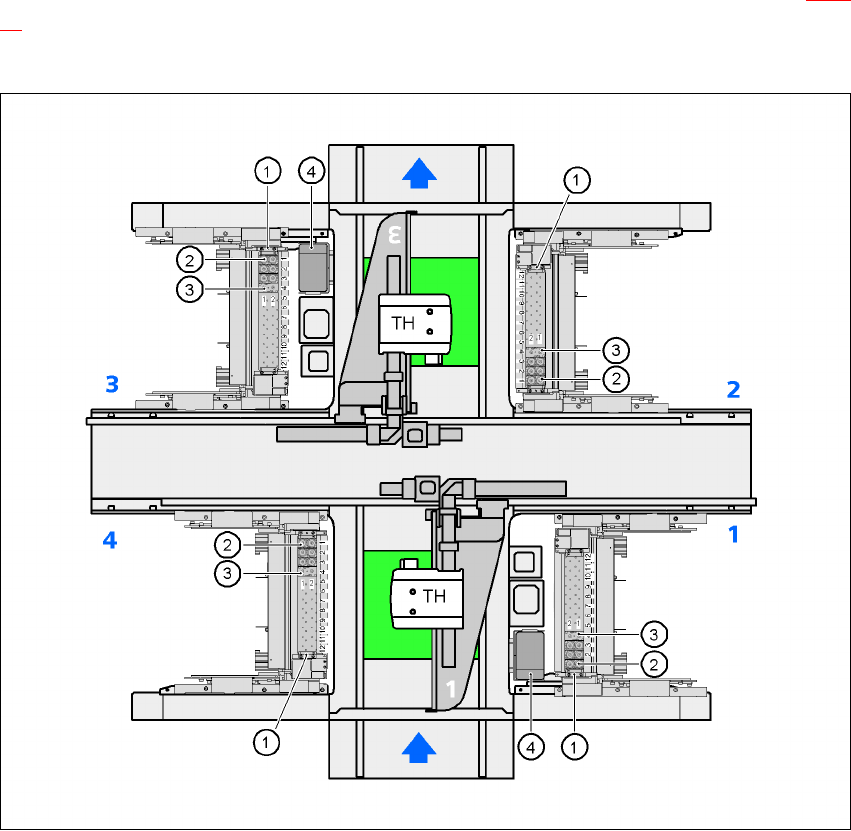
7.1.3.2 Position of the nozzle changers for the TwinHead on the HF machine
A nozzle changer for the TwinHead may be installed at locations 1, 2, 3 and 4 (item 1 in Fig. 7.1 -
18). This gives a total capacity of 4 nozzle changers with 48 magazines and a total of 96 nozzle
holders.
7
Fig. 7.1 - 18 Position of the nozzle changers for the TwinHead on the HF machine
(1) Nozzle changer
(2) Standard magazine
(3) Magazine for special nozzles or grippers
(4) Component reject bin
7
7
User manual SIPLACE HF series 7 Station extensions
Software Version SR.50x.xx 01/2006 US Edition 7.1 Nozzle changer
313
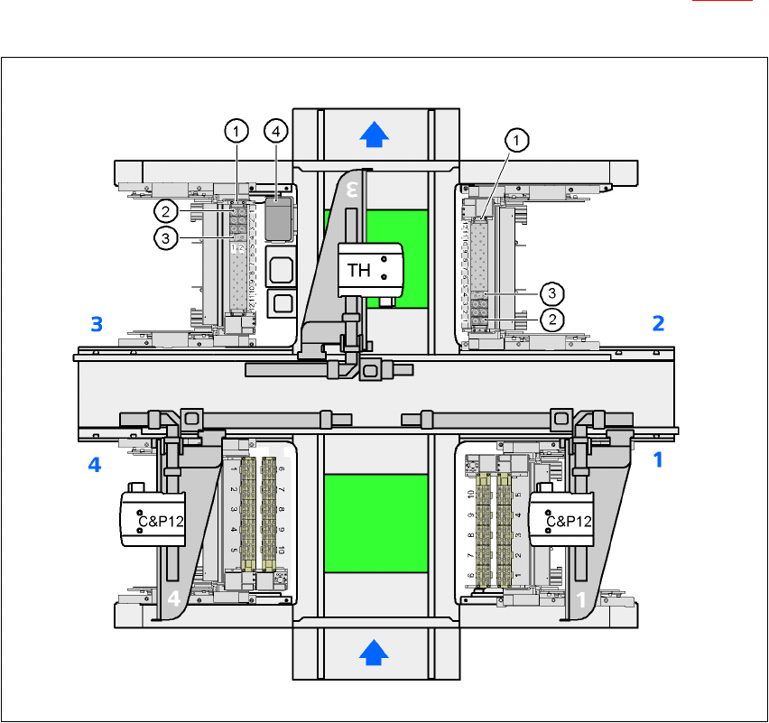
7.1.3.3 Position of the nozzle changers for the TwinHead on the HF/3 machine
A nozzle changer for the TwinHead may be installed at locations 2 and 3 (item 1 in Fig. 7.1 - 19).
This gives a total capacity of 2 nozzle changers and a total of 48 nozzle holders.
7
Fig. 7.1 - 19 Position of the nozzle changers for the TwinHead on the HF/3 machine
(1) Nozzle changer
(2) Standard magazine
(3) Magazine for special nozzles or grippers
(4) Component reject bin
7 Station extensions User manual SIPLACE HF series
7.1 Nozzle changer Software Version SR.50x.xx 01/2006 US Edition
314
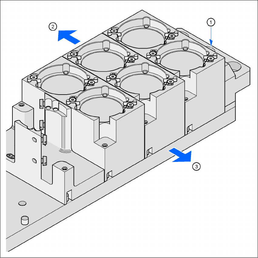
7.1.3.4 Assembly
The nozzle changer is fixed to the component trolley docking unit.
7
Fig. 7.1 - 20 Assembly position
(1) Marking hole
(2) Operator side
(3) Arrow pointing toward the PCB conveyor
7
Æ Align the nozzle changer so that the marking hole (item 1) is on the left, as viewed by the op-
erator.