00193922-03.pdf - 第320页
7 Station extensions User manual SIPLA CE HF series 7.3 Component c amera for the TwinHead, FC came ra Software Version S R.50x.xx 01/ 2006 US Edition 320 7.3.1.3 Pos ition of the component vision cameras for the T winHe…
User manual SIPLACE HF series 7 Station extensions
Software Version SR.50x.xx 01/2006 US Edition 7.3 Component camera for the TwinHead, FC camera
319
7.3.1.2 Position of the component vision cameras for the TwinHead on the
HF placement machine
7
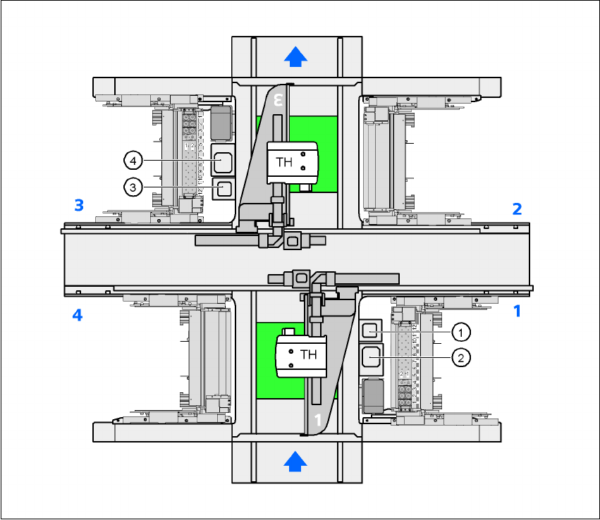
Fig. 7.3 - 2 Position of the component vision cameras for the TwinHead on the HF placement machine
(1) Assembly position for the CO vision camera (stationary, P&P (type 20) 8 x 8), location 1
(2) Assembly position for the CO vision camera (stationary, P&P (type 22) 50 x 40), location 1
(3) Assembly position for the CO vision camera (stationary, P&P (type 20) 8 x 8), location 3
(4) Assembly position for the CO vision camera (stationary, P&P (type 22) 50 x 40), location 3
7 Station extensions User manual SIPLACE HF series
7.3 Component camera for the TwinHead, FC camera Software Version SR.50x.xx 01/2006 US Edition
320
7.3.1.3 Position of the component vision cameras for the TwinHead on the
HF/3 placement machine
7
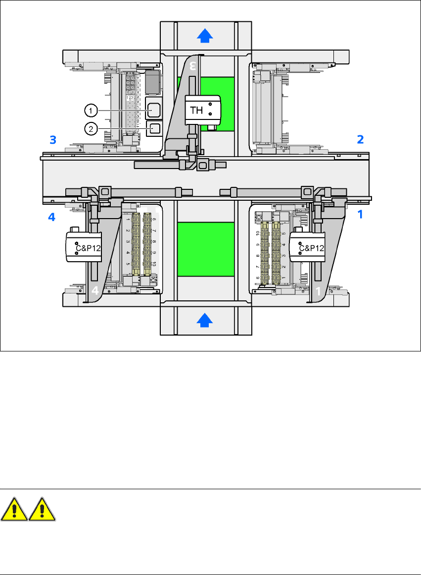
Fig. 7.3 - 3 Position of the component vision cameras for the TwinHead on the HF/3 placement machine
7
(1) Assembly position for the CO vision camera (stationary, P&P (type 22) 50 x 40), location 3
(2) Assembly position for the CO vision camera (stationary, P&P (type 20) 8 x 8), location 3
7.3.2 Safety instructions for the TwinHead component cameras during
a placement head change
WARNING 7
When the placement head is changed from the TwinHead to the Collect&Place head, the Twin-
Head's component vision cameras (stationary, P&P, type 22, 50 x 40, and type 20, 8 x 8) must be
removed, otherwise the Collect&Place head will collide with the camera housings.
User manual SIPLACE HF series 7 Station extensions
Software Version SR.50x.xx 01/2006 US Edition 7.4 Component barcode scanner
321
7.4 Component barcode scanner
7.4.1 General
Item no. 00119683-xx
With the placement system, a barcode scanner can be used to check that the track allocation is
correct and to read component data from component reels. A barcode scanner can be installed
on both of the operator panels on the placement system. A retrofit kit contains two component bar-
code scanners.
7
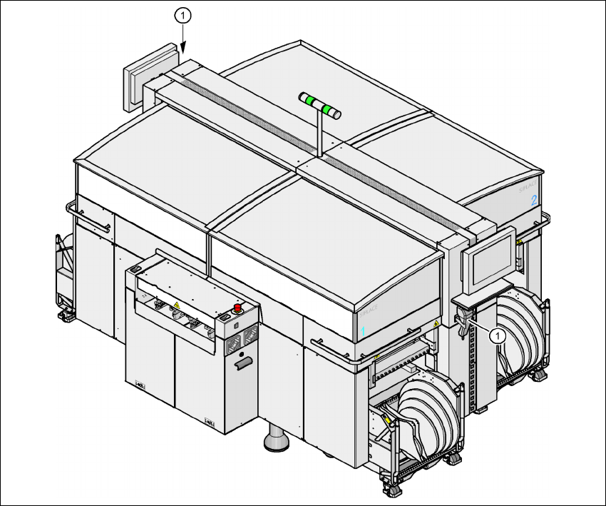
Fig. 7.4 - 1 Component barcode scanner
(1) Barcode scanner
Track allocation 7
Four-digit barcode strips are attached to the lateral safety screens for the purposes of track allo-
cation. The first digit is used to identify the component table (1, 2, 3, or 4), while the remaining