00193922-03.pdf - 第327页
User manual SIPLAC E HF series 7 Station extensions Software Vers ion SR.50x.xx 01/2006 US Edition 7.5 PCB barcode scanner 327 7.5.6 Assembly options for the PCB barc ode scanner 7 Fig. 7.5 - 3 Assembly options for the P…
7 Station extensions User manual SIPLACE HF series
7.5 PCB barcode scanner Software Version SR.50x.xx 01/2006 US Edition
326
7
7
7
7
7
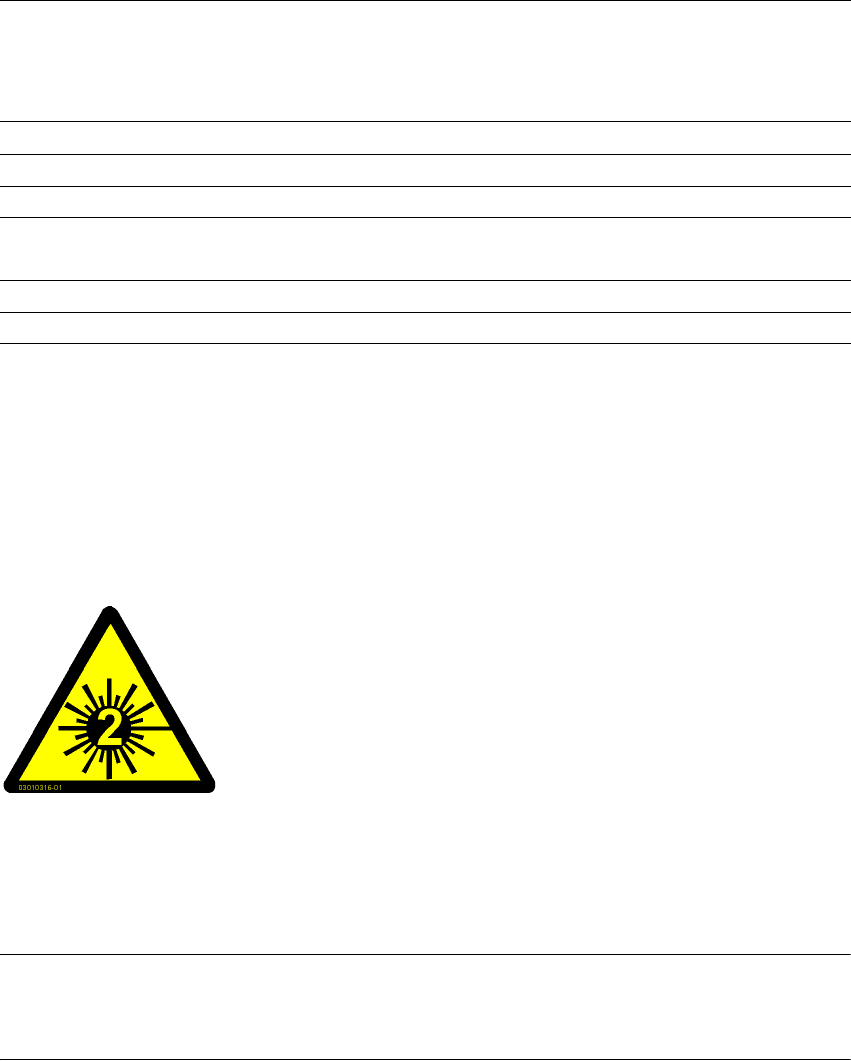
7.5.5 Warning label W216 on the cover of the PCB input side
7
Warning label W216 "Laser class 2" on the cover of the PCB input side,
item no. 03010316-01 (number per placement machine: 1)
PLEASE NOTE 7
When you install a PCB barcode scanner on the placement machine, you must attach laser
warning label W206 contained in the retrofit kit to the cover on the PCB input side.
7
1D barcode length
Single conveyor
Dual conveyor, asynchronous
Dual conveyor, synchronous
Max. 40 characters
Max. 40 characters
Max. 2 x 12 characters
Optical display 4 x LED function display
Audible indicator Buzzer
Data interface RS232, RS 422/485, Ethernet
Electrical connection 15-pin D-Sub HD connector
RJ45 connector 10baseT
Operating voltage 10 VDC ... 30 VDC
Degree of protection Class 3
7
7
7
7
7
7
LASER RADIATION!
Do not look into beam
Laser class 2
User manual SIPLACE HF series 7 Station extensions
Software Version SR.50x.xx 01/2006 US Edition 7.5 PCB barcode scanner
327
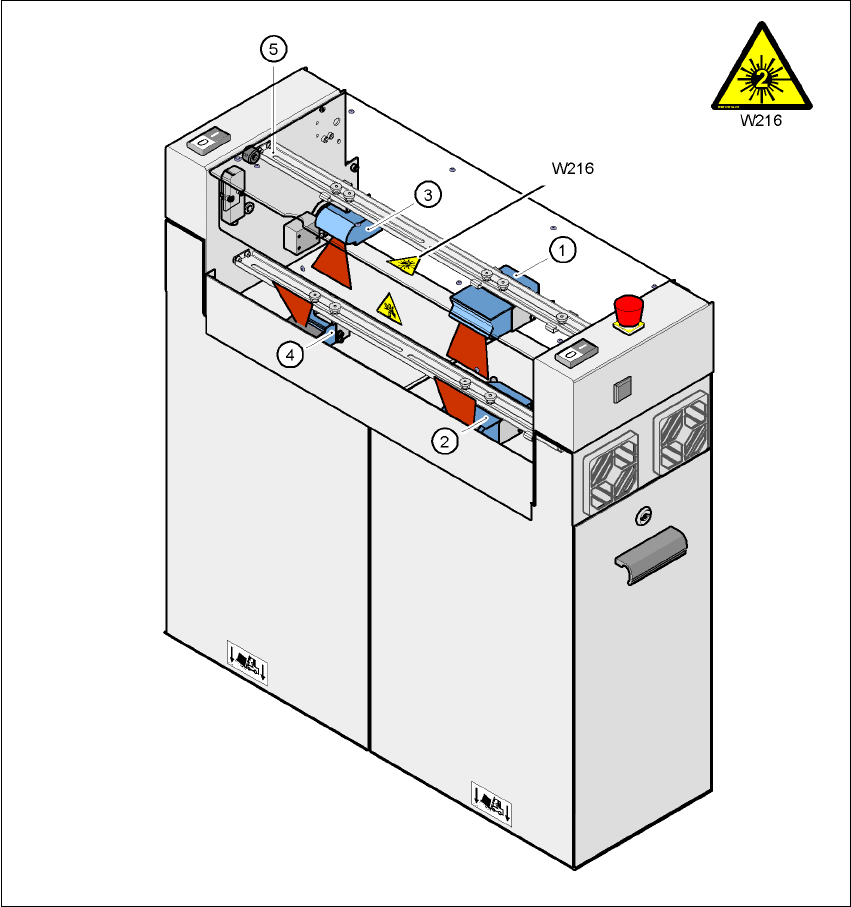
7.5.6 Assembly options for the PCB barcode scanner
7
Fig. 7.5 - 3 Assembly options for the PCB barcode scanner
(1) 2D barcode scanner "topside"
(2) 2D barcode scanner "underside"
(3) 1D barcode scanner "topside"
(4) 1D barcode scanner "underside"
(5) Assembly rail
Pos. W216, item no. 03010316-01
7 Station extensions User manual SIPLACE HF series
7.5 PCB barcode scanner Software Version SR.50x.xx 01/2006 US Edition
328
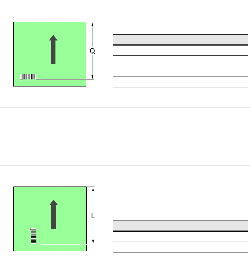
7.5.7 Positioning PCB barcode labels on the PCB
7.5.7.1 Positioning along the long side of the PCB -
Scanning beam
across
the direction of travel
7
Fig. 7.5 - 4 Positioning along the long side of the PCB - Scanning beam across the direction of travel
7.5.7.2 Positioning along the long side of the PCB -
Scanning beam
along
the direction of travel
7
Fig. 7.5 - 5 Positioning along the long side of the PCB - Scanning beam along the direction of travel
PCB barcode scanner Q [mm]
2D topside 390
1D topside 390
2D underside 430
1D underside 430
PCB barcode scanner L [mm]
1D topside 320 - 350
1D underside 380 - 410