00193922-03.pdf - 第331页
User manual SIPLAC E HF series 7 Station extensions Software Vers ion SR.50x.xx 01/2006 US E dition 7. 6 Multicolor PCB came ra (type 18) 331 7.6 Multicolor PCB ca mera (type 18) Item no. 001 196 74-xx Multicolor PCB vis…
7 Station extensions User manual SIPLACE HF series
7.5 PCB barcode scanner Software Version SR.50x.xx 01/2006 US Edition
330
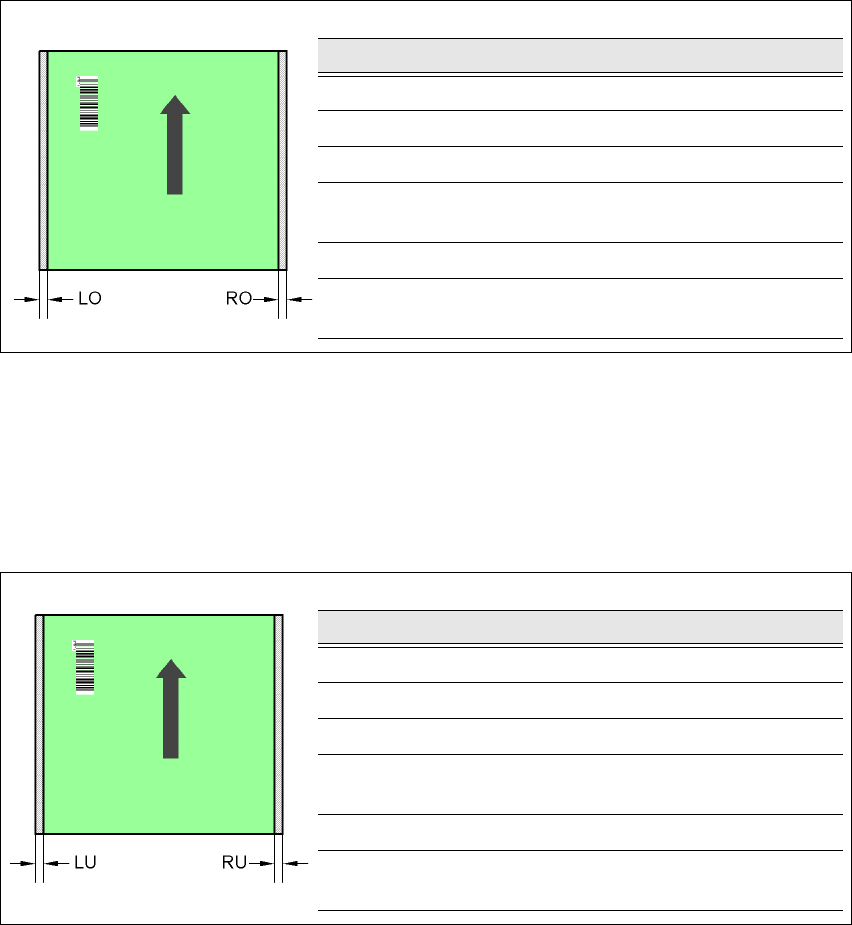
7.5.7.5 Positioning along the width of the PCB -
Scanning beam
along
the direction of travel,
PCB barcode scanner 1D
topside
7
Fig. 7.5 - 8 Positioning along the width of the PCB - Scanning beam along the direction of travel
PCB barcode scanner 1D topside
7
7.5.7.6 Positioning along the width of the PCB -
Scanning beam
along
the direction of travel,
PCB barcode scanner 1D
underside
7
Fig. 7.5 - 9 Positioning along the width of the PCB - Scanning beam along the direction of travel
PCB barcode scanner 1D underside
SC Single conveyor
DC1 Dual conveyor, track 1
DC2 Dual conveyor, track 2
SM1 Dual conveyor in Single conveyor mode, track 1
SM2 Dual conveyor in Single conveyor mode, track 2
PCB dimensions/conveyor LO [mm] RO [mm]
460 mm / SC 3 20
508 mm / SC 3 44
216 mm / DC1 3 24
250 mm / DC1
450 mm / SM1
358
216 mm / DC2 3 3
250 mm / DC2
450 mm / SM2
33
PCB dimensions/conveyor LU [mm] RU [mm]
460 mm / SC 20 3
508 mm / SC 44 3
216 mm / DC1 3 3
250 mm / DC1
450 mm / SM1
33
216 mm / DC2 24 3
250 mm / DC2
450 mm / SM2
58 3
User manual SIPLACE HF series 7 Station extensions
Software Version SR.50x.xx 01/2006 US Edition 7.6 Multicolor PCB camera (type 18)
331
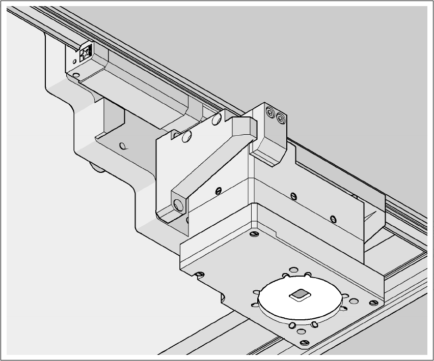
7.6 Multicolor PCB camera (type 18)
Item no. 00119674-xx Multicolor PCB vision module HF/3
Item no. 00119676-xx Multicolor PCB vision module HF
7.6.1 General
As an option, a multicolor PCB camera can be installed in place of the sub-gantry camera. The
multicolor PCB camera offers four different types of illumination. This greatly increases fiducial de-
tection and thus the centering accuracy.
7
Fig. 7.6 - 1 Multi-color PCB camera
7 Station extensions User manual SIPLACE HF series
7.6 Multicolor PCB camera (type 18) Software Version SR.50x.xx 01/2006 US Edition
332
7.6.2 Type of illumination
The following types of illumination can be selected on the multicolor PCB camera:
– Standard lighting
This mixture of white and infrared lighting can be used to detect a broad range of fiducials.
The image contrast can be improved by varying the illumination, thus optimizing the centering
of different fiducials.
– White lighting
This type of illumination is used for standard PCBs with tinned fiducials.
– Blue oblique lighting
In most cases, this can be used to greatly improve the contrast with bright fiducials on a light
base material, such as ceramic or CEM. Fiducials covered with solder resist can also be de-
tected better on a light background.
– Infrared lighting
This type of illumination is particularly useful for fiducials that are covered with solder resist
or for fiducials on flex materials. It is also sometimes possible to improve detection of silver/
platinum fiducials on ceramic. This should be tested by carrying out a test centering or place-
ment run.