00193922-03.pdf - 第336页
7 Station extensions User manual SIPLA CE HF series 7.9 Optional mechanical s topper Software Version SR.50x.xx 01/2006 US E dition 336 7.9 Optional mechanical stopper Item no. 001 1965 7-xx Optional mec hanical stopper …
User manual SIPLACE HF series 7 Station extensions
Software Version SR.50x.xx 01/2006 US Edition 7.8 PCB alignment
335
7.8.2 Description of the functions
The PCB is transported into the placement area until the laser light barrier triggers the stop signal
for the PCB conveyor. The lifting table with the PCB stops then moves up into a position in which
the PCB is not yet clamped and can still be moved by the conveyor belts. The two PCB stops are
level with the PCB, and the PCB supports (magnetic pins) are already in contact with the PCB.
The two conveyor belts move the PCB against the PCB stops and align them at the same time.
The lifting table then moves into its top end position, clamps the PCB and releases it from the PCB
stops so as not to affect the placement process. After the placement process, the lifting table and
PCB alignment are lowered and the PCB is moved on.
7
7 Station extensions User manual SIPLACE HF series
7.9 Optional mechanical stopper Software Version SR.50x.xx 01/2006 US Edition
336
7.9 Optional mechanical stopper
Item no. 00119657-xx Optional mechanical stopper HF/X series, single conveyor
Item no. 00119658-xx Optional mechanical stopper HF/X series, dual conveyor
7.9.1 General
The optional mechanical stopper was developed for the X-series, HF series, HS-60 and S-27 HM
placement machines. These are equipped as standard with the modular PCB conveyor and
elec-
tronically-controlled
PCB stoppers with laser light barriers.
The HS-50, F5 HM and S-25 HM placement machine models, on the other hand, have a PCB con-
veyor with
mechanical
stopper.
Install the optional mechanical stopper on placement machines with modular PCB conveyor if you
want to run the machines in a mixed line. This will make it possible to define a standardized stop-
per position for the PCBs on both PCB conveyor variants.
7
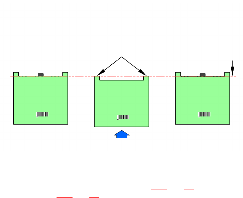
Fig. 7.9 - 1 PCB stop positions on HS-50, F5 HM, S-25 HM and HF series machines
7.9.2 Technical data
The technical data for the PCB single conveyor (see section 3.12.2, page 151) and the PCB dual
conveyor (see section 3.13.2
, page 154). Only the value for the minimum PCB width is increased
from 50 mm to 56 mm due to the design.
Software version SW 505.03 is needed in order to use this option.
PCB transport direction
PCB PCB PCB
HS-50/F5-HM/S25 HM
with mechanical stopper
(standard)
HF series
with electronically-
controlled stopper
(laser light barrier)
HF series
with optional
mechanical stopper
Laser light barrier Stop position for the PCB
User manual SIPLACE HF series 7 Station extensions
Software Version SR.50x.xx 01/2006 US Edition 7.9 Optional mechanical stopper
337
7.9.3 Properties
The optional mechanical stopper can only be installed in the placement areas. It can be moved
freely over the entire PCB conveyor width. If the conveyor width is reduced, the stopper is moved
as well. The minimum PCB conveyor width of 56 mm is monitored by a sensor. The "Optional me-
chanical stopper" and "Long board" option can be combined. This is not possible for ceramic sub-
strate centering, the PCB alignment option and vacuum tooling.
7.9.4 Description of the functions
7
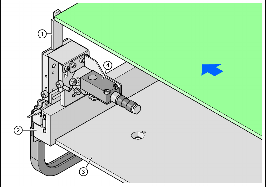
Fig. 7.9 - 2 Optional mechanical stopper
(1) Stopper extended
(2) Guide rail
(3) Lifting table
(4) Sonar sensor
The mechanical stopper (item 1) is extended as the PCB moves into the placement area. The so-
nar sensor (item 4) registers the incoming PCB and gives the signal to reduce the conveyor speed.
As a result, the PCB is stopped at the stopper at reduced speed and thus with low forces.
The mechanical stopper can be positioned freely along the guide rail (item 2) between the panels
of the PCB conveyor.
PCB transport direction
PCB