00193922-03.pdf - 第338页
7 Station extensions User manual SIPLA CE HF series 7.10 Feeder mod ule cover flap Software Version SR.50x.xx 01/2006 US Edition 338 7.10 Feede r module cover flap Item no. 001 1961 0-xx F eeder m odule co ver flap HF 2/…
User manual SIPLACE HF series 7 Station extensions
Software Version SR.50x.xx 01/2006 US Edition 7.9 Optional mechanical stopper
337
7.9.3 Properties
The optional mechanical stopper can only be installed in the placement areas. It can be moved
freely over the entire PCB conveyor width. If the conveyor width is reduced, the stopper is moved
as well. The minimum PCB conveyor width of 56 mm is monitored by a sensor. The "Optional me-
chanical stopper" and "Long board" option can be combined. This is not possible for ceramic sub-
strate centering, the PCB alignment option and vacuum tooling.
7.9.4 Description of the functions
7
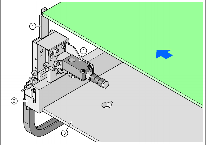
Fig. 7.9 - 2 Optional mechanical stopper
(1) Stopper extended
(2) Guide rail
(3) Lifting table
(4) Sonar sensor
The mechanical stopper (item 1) is extended as the PCB moves into the placement area. The so-
nar sensor (item 4) registers the incoming PCB and gives the signal to reduce the conveyor speed.
As a result, the PCB is stopped at the stopper at reduced speed and thus with low forces.
The mechanical stopper can be positioned freely along the guide rail (item 2) between the panels
of the PCB conveyor.
PCB transport direction
PCB
7 Station extensions User manual SIPLACE HF series
7.10 Feeder module cover flap Software Version SR.50x.xx 01/2006 US Edition
338
7.10 Feeder module cover flap
Item no. 00119610-xx Feeder module cover flap HF 2/4 for locations 2 or 4
Item no. 00119633-xx Feeder module cover flap HF 1/3 for locations 1 or 3
The feeder module cover flap is installed over the component feeder area. It is designed to prevent
a head crash with an upright feeder module retainer that has not been engaged correctly. The
feeder module cover flap can also prevent the front panel of feeder modules entering the place-
ment head traveling range due to incorrect operation.
7
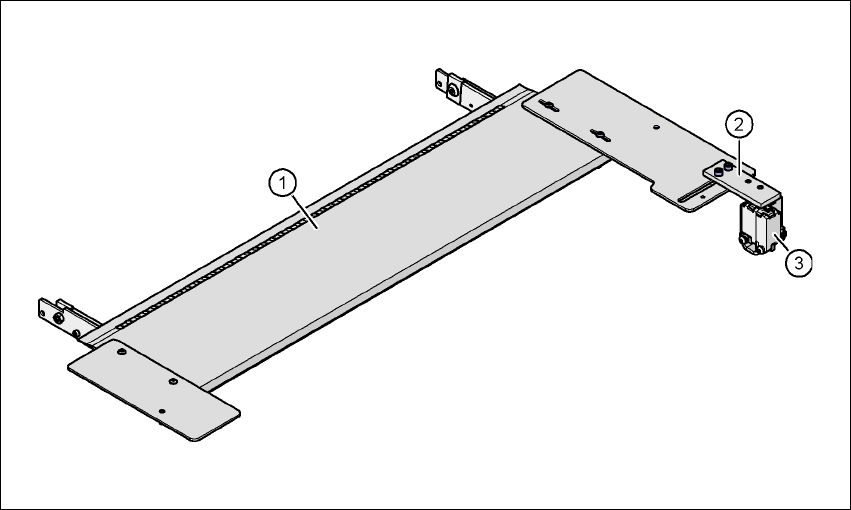
Fig. 7.10 - 1 Feeder module cover flap for locations 1 and 3
7
(1) Feeder module cover flap
(2) Mechanical lock
(3) Switch in the emergency stop circuit
The switch for the feeder module cover flap is looped into the emergency stop circuit. The feeder
module cover flap must be locked mechanically, which causes the switch to close the open emer-
gency stop circuit.
User manual SIPLACE HF series 7 Station extensions
Software Version SR.50x.xx 01/2006 US Edition 7.11 Component sensor
339
7.11 Component sensor
Item no. 00118021-xx
7
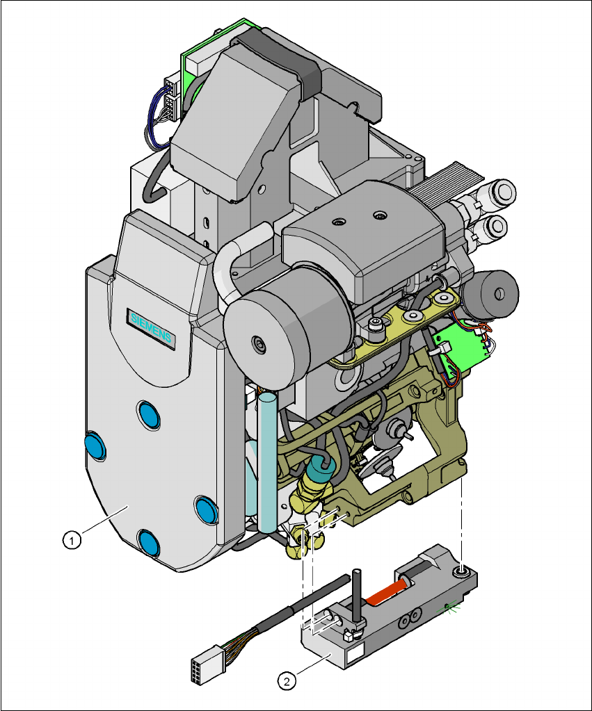
Fig. 7.11 - 1 Placement head with component sensor
(1) Placement head
(2) Component sensor