00193922-03.pdf - 第346页
7 Station extensions User manual SIPLA CE HF series 7.12 Coplanarity laser module Software Vers ion SR.50x.xx 01/2006 US E dition 346 7.12. 4 Overvie w 7.12.4.1 Analysis un it The copl anarity laser module consists of tw…
User manual SIPLACE HF series 7 Station extensions
Software Version SR.50x.xx 01/2006 US Edition 7.12 Coplanarity laser module
345
7
Fig. 7.12 - 3 Identification for laser class 1
The interlock line is connected in series with the switches for the protective hood. This protective
function is maintained even if the key switch is turned to bypass the protection. This means that
the laser module can only be used if the machine is closed!
DANGER
The safety guarantee is automatically invalidated if safety devices are modified or bypassed!
The user must also conform to the guidelines issued by the umbrella organization of employers'
liability insurance associations – VBG 93 – i.e
- Registration with the employers’ liability insurance association
- Appointment of a laser protection officer
- Drawing up guidelines for use of the module 7
Laser class 1

7 Station extensions User manual SIPLACE HF series
7.12 Coplanarity laser module Software Version SR.50x.xx 01/2006 US Edition
346
7.12.4 Overview
7.12.4.1 Analysis unit
The coplanarity laser module consists of two components: the analysis unit with its control section,
and the laser module. The analysis unit is located in the computer unit (see Fig. 7.12 - 4
). The
operating state is indicated by three green LEDs on the front panel of the analysis unit:
7
Press the RESET key to initialize the coplanarity laser module.
7.12.4.2 Laser module
The laser module is fixed to a supporting frame (see Fig. 7.12 - 5).
Two red LEDs and one green LED signal the operating states of the laser module:
7
LED (see Fig. 7.12 - 4)On Off
1 green 5 operating voltage No voltage
2 green 12V operating voltage No voltage
3 green Laser module in use Laser module switched off
LED (see Fig. 7.12 - 5)On Off
4 red
OUT OF RANGE
(outside the measuring range)
–
5 red
POOR TARGET
(component is insufficiently reflective)
–
6 green Laser module in use Laser module switched off
User manual SIPLACE HF series 7 Station extensions
Software Version SR.50x.xx 01/2006 US Edition 7.12 Coplanarity laser module
347
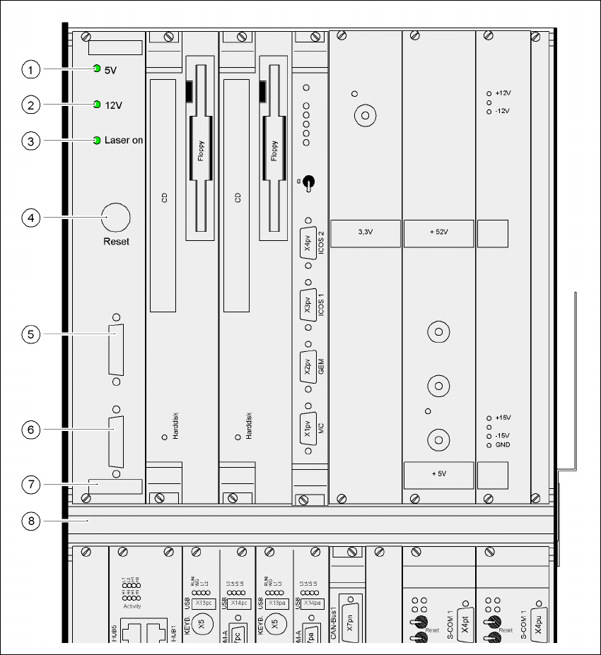
Fig. 7.12 - 4 Coplanarity laser module overview
(1) Green LED: 5V operating voltage
(2) Green LED: 12V operating voltage
(3) Green LED: laser module switched on
(4) RESET key
(5) SUB-D plug, 9-pin, COM2: to the machine controller
(6) SUB-D plug, 15-pin: to the laser module
(7) Analysis unit with control section
(8) Computer unit