00193922-03.pdf - 第51页
User manual SIPLAC E HF series 2 Operational safety Software Vers ion SR.50x.xx 01/2006 US Ed ition 2.3 Laser classification 51 2.3 Las er classi ficat ion 2.3.1 Laser cla ss 1 2.3.1.1 Classifi cation of the whole machin…
2 Operational safety User manual SIPLACE HF series
2.2 Warning labels Software Version SR.50x.xx 01/2006 US Edition
50
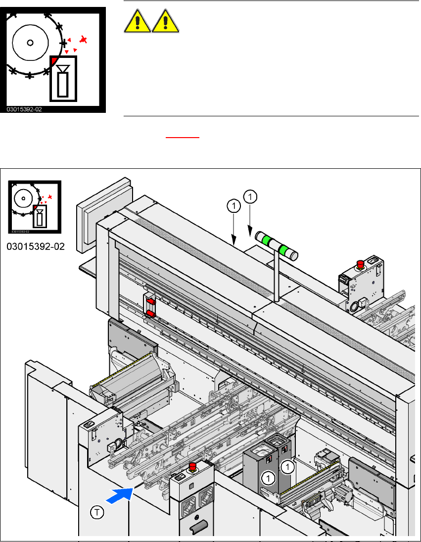
2.2.12 "Head crash" information plate on the component cameras of the TwinHead
"Head crash" information plate in Fig. 2.2 - 16, item no. 03015392-02
(number per placement system: 2 for the HF/3, 4 for the HF)
2
Fig. 2.2 - 16 "Head crash" information plate on the component cameras of the TwinHead
2
(1) "Head crash" information plate on the component cameras of the TwinHead
WARNING RISK OF HEAD CRASH 2
When the placement head is changed from the TwinHead to the
Collect&Place head, the TwinHead's component vision cameras
(stationary, P&P, type 22, 50 x 40, and type 20, 8 x 8) must be
removed, otherwise the Collect&Place head will collide with the
camera housings.
User manual SIPLACE HF series 2 Operational safety
Software Version SR.50x.xx 01/2006 US Edition 2.3 Laser classification
51
2.3 Laser classification
2.3.1 Laser class 1
2.3.1.1 Classification of the whole machine
2
PLEASE NOTE: 2
Modules in laser classes 1 and 1M are not identified.
2.3.1.2 Classification of the camera systems
2
2.3.2 Laser class 1M
Do not look directly at this with optical instruments!
2
2
All installed camera systems and the whole machine when ready for operation
are assigned to laser class 1.
The laser classes are determined according to DIN EN 60825-1:2001.
2
The following camera systems are assigned to laser class 1:
– Multicolor PCB camera (type 18)
– Component vision camera for the SIPLACE TwinHead
Stationary component vision camera P&P (type 22) 50 x 40
Stationary component vision camera P&P (type 20) 8 x 8
2
The following camera systems are assigned to laser class 1M:
– 24 x 24 component camera on the 12-segment Collect&Place head
– 39 x 39 component camera on the 6-segment Collect&Place head
– 16 x 16 DCA camera on the 6-segment or 12-segment Collect&Place head
2 Operational safety User manual SIPLACE HF series
2.4 Safety instructions for transporting the machine Software Version SR.50x.xx 01/2006 US Edition
52
2.3.3 Laser class 2
The following modules are assigned to laser class 2:
– Laser light barrier, placement area 1 in the PCB conveyor
– Laser light barrier, placement area 2 in the PCB conveyor
– PCB barcode scanner
– Coplanarity laser module
2
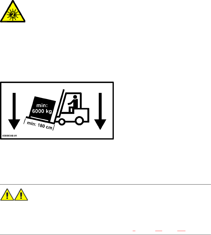
2.4 Safety instructions for transporting the machine
2
Use a fork-lift truck with the following specification to carry the machine:
Fork length: min. 1800 mm
Carrying power: min. 6000 kg
Clear width between forks: min. 350 mm 2
WARNING
RISK OF TIPPING 2
If the required specification cannot be applied to the fork-lift, there is a risk that the fork-lift will tip
over when carrying the placement machine.
Transporting the placement machine is described in chapter 4, section 4.2, page 159.
2
Laser radiation
Do not look into beam!