00193922-03.pdf - 第63页
User manual SIPLAC E HF series 2 Operational safety Software Vers ion SR.50x.xx 01/2006 US Edition 2.6 Safety equipment 63 2.6.2 Swi tches and buttons on the pla cement machi ne 2.6.2.1 Position of swit ches and buttons …
2 Operational safety User manual SIPLACE HF series
2.6 Safety equipment Software Version SR.50x.xx 01/2006 US Edition
62
conveyor is protected by covers, which can be pivoted upwards, over the input and output belts
and hand guards on both belts.
Function 2
The main power supply to the gantry axes is interrupted immediately if one of the protective covers
is swiveled up or one of the cover flaps on the PCB conveyor is raised. The gantry axes stop mov-
ing. The message "Close cover" is displayed on the screen.
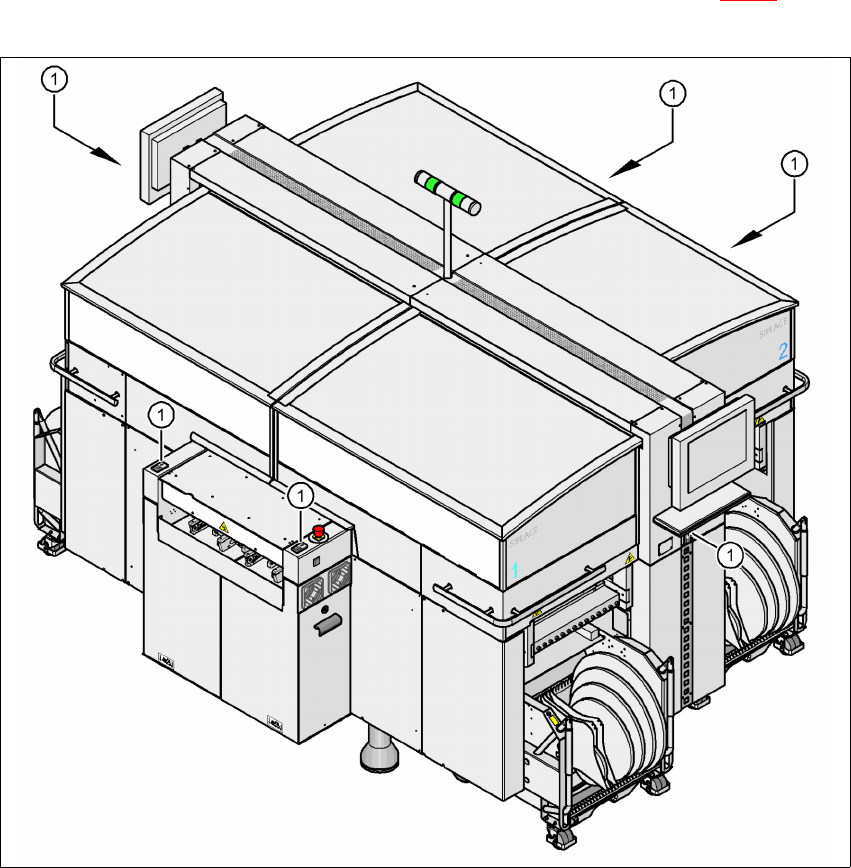
Æ Close the protective covers and press one of the Start buttons (Pos. 1 in Fig. 2.6 - 2) to con-
tinue placement.
2
Fig. 2.6 - 2 Position of the Start buttons (white) on the machine
(1) Start button (white) on the machine
User manual SIPLACE HF series 2 Operational safety
Software Version SR.50x.xx 01/2006 US Edition 2.6 Safety equipment
63
2.6.2 Switches and buttons on the placement machine
2.6.2.1 Position of switches and buttons on the placement machine
2
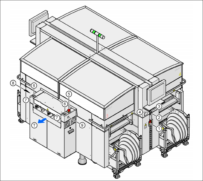
Fig. 2.6 - 3 Position of switches and buttons - View of the PCB output side
2
(1) Main power switch
(2) Stop button (black) on the operator panel on the power supply side
(3) Start button (white) on the operator panel on the power supply side
(4) Component counter on the operator panel on the power supply side
(5) Emergency stop button on the output side
(6) Start button (white) on the output side
(7) Stop button (white) on the output side
(8) Button (black) for docking the component trolley in or out, location 2
(9) Button (black) for docking the component trolley in or out, location 3
(T) PCB transport direction
2 Operational safety User manual SIPLACE HF series
2.6 Safety equipment Software Version SR.50x.xx 01/2006 US Edition
64
2
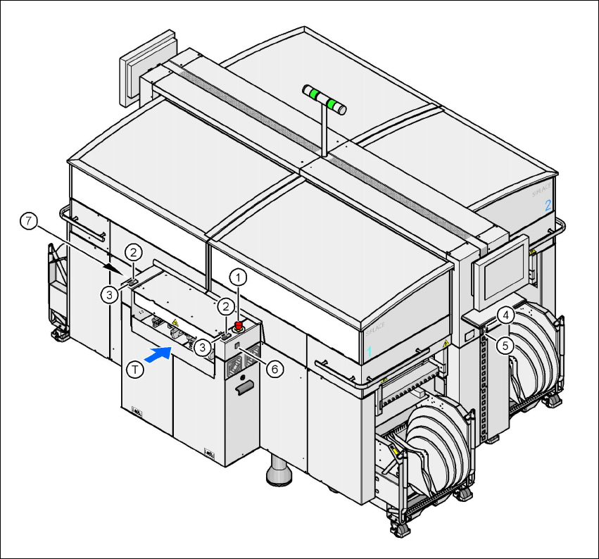
Fig. 2.6 - 4 Position of switches and buttons - View of the PCB input side
2
(1) Emergency stop button on the input side
(2) Start button (white) on the input side
(3) Stop button (white) on the input side
(4) Start button (white) on the operator panel on the compressed air unit side
(5) Stop button (black) on the operator panel on the compressed air unit side
(6) Button (black) for docking the component trolley in or out, location 1
(7) Button (black) for docking the component trolley in or out, location 4
(T) PCB transport direction