00193922-03.pdf - 第78页
2 Operational safety User manual SIPLACE HF series 2.9 Energy state of the machine af ter switching off at t he main power switch Software Version SR.50x.xx 01/2006 US E dition 78 2.9 Energy st ate of the mach ine af ter…
User manual SIPLACE HF series 2 Operational safety
Software Version SR.50x.xx 01/2006 US Edition 2.8 Disabling the compressed air supply and discharging the pressure
77
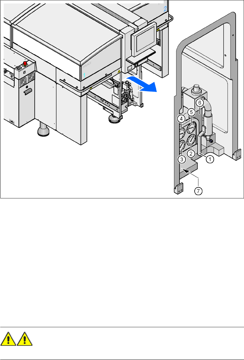
Fig. 2.8 - 1 Compressed air unit on the placement system
2
(1) Stop valve
(2) Manometer for the machine component supply pressure
Desired pressure: 0.48 ± 0.025 MPa, 4.8 ± 0.25 bar (display range 0 - 0.6 MPa, 0 - 6 bar)
(3) Manometer for the gantry distributor supply pressure
Desired pressure: 0.46 ± 0.01 MPa, 4.6 ± 0.1 bar (display range 0 - 0.6 MPa, 0 - 6 bar)
(4) Manometer for the bulk case feeder modules supply pressure
Desired pressure: 0.25 ± 0.05 MPa, 2.5 ± 0.5 bar (display range 0 - 0.6 MPa, 0 - 6 bar)
(5) Manometer for the input pressure
Desired pressure: 0.5 - 1.0 MPa, 5 - 10 bar (display range: 0 - 1.0 MPa, 0 - 10 bar)
(6) Compressed air filter
(7) Hexagon socket head screw for fixing the pneumatic board
WARNING
NEVER detach compressed air lines while they are still pressurized. Risk of injury. 2
2 Operational safety User manual SIPLACE HF series
2.9 Energy state of the machine after switching off at the main power switch Software Version SR.50x.xx 01/2006 US Edition
78
2.9 Energy state of the machine after switching off at
the main power switch
2
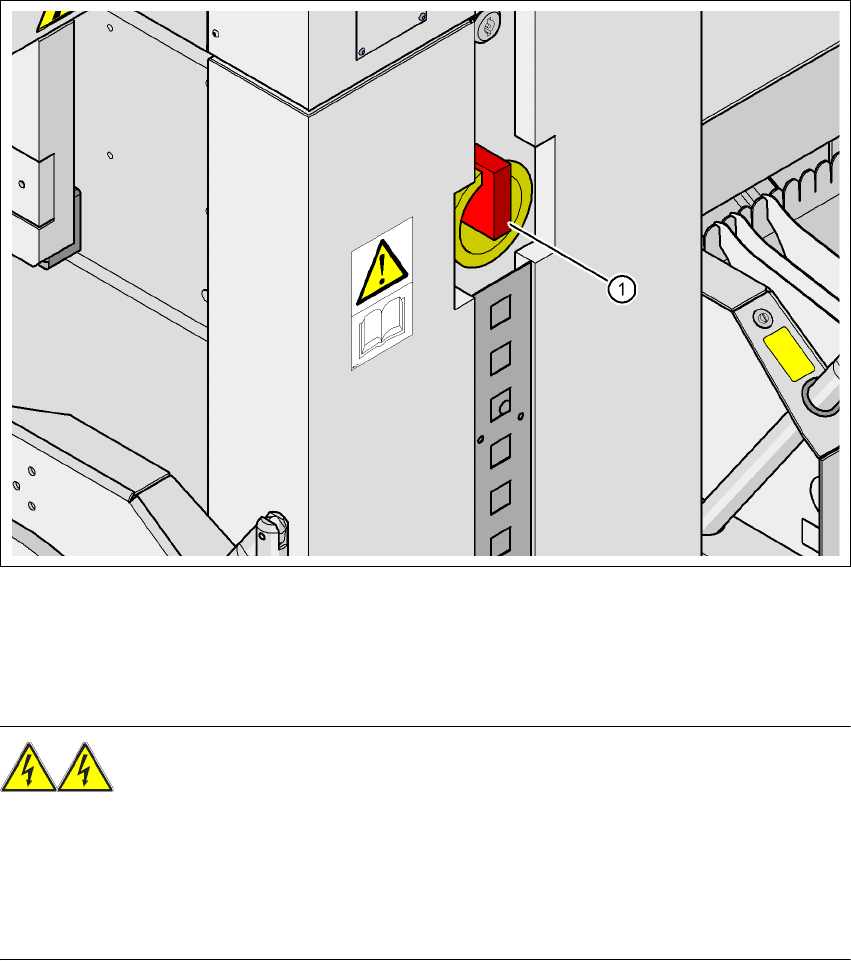
Fig. 2.9 - 1 Position of the power supply on the machine
2
WARNING
The placement system is supplied with 3 x 208 VAC, 3 x 230 VAC, 3 x 380 VAC, 3 x 400 VAC or
3 x 415 VAC ± 5 %, 50/60 Hz mains voltage. This means that some parts of the system carry po-
tentially lethal voltages - even when switched off at the main power switch. Incorrect handling of
the placement system can therefore result in death or severe injury or considerable damage to
equipment. 2
Æ Always follow the applicable accident prevention and DIN regulations (particularly DIN EN 60
204, part 1).
Æ The guard over the power supply unit must ONLY be opened by appropriately qualified and
trained personnel.
(1) Main power switch
User manual SIPLACE HF series 2 Operational safety
Software Version SR.50x.xx 01/2006 US Edition 2.9 Energy state of the machine after switching off at the main power switch
79
2
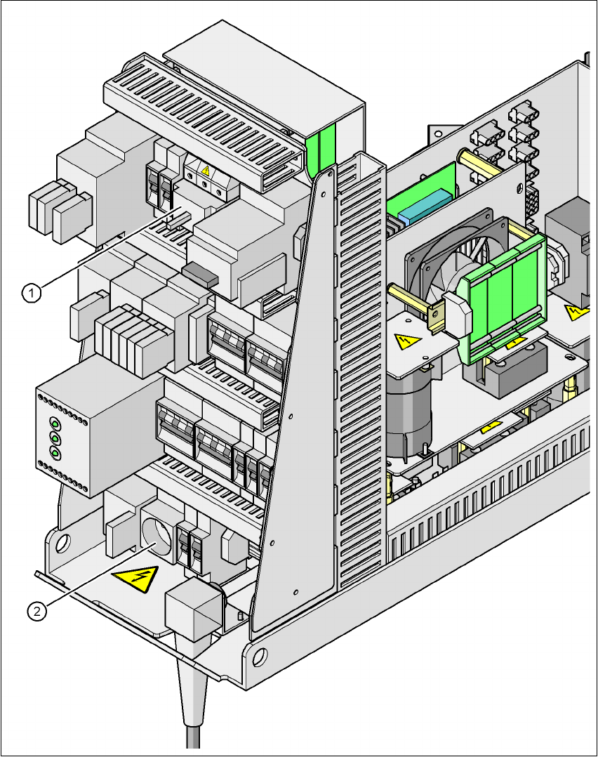
Fig. 2.9 - 2 Position of main power switch and service socket
2
(1) Main power switch
(2) Service socket