00193922-03.pdf - 第79页
User manual SIPLAC E HF series 2 Operational safety Software Vers ion SR.50x.xx 01/2006 US Ed ition 2.9 Energy state of the machine af ter switching off at t he main power sw itch 79 2 Fig. 2.9 - 2 Position of main power…
2 Operational safety User manual SIPLACE HF series
2.9 Energy state of the machine after switching off at the main power switch Software Version SR.50x.xx 01/2006 US Edition
78
2.9 Energy state of the machine after switching off at
the main power switch
2
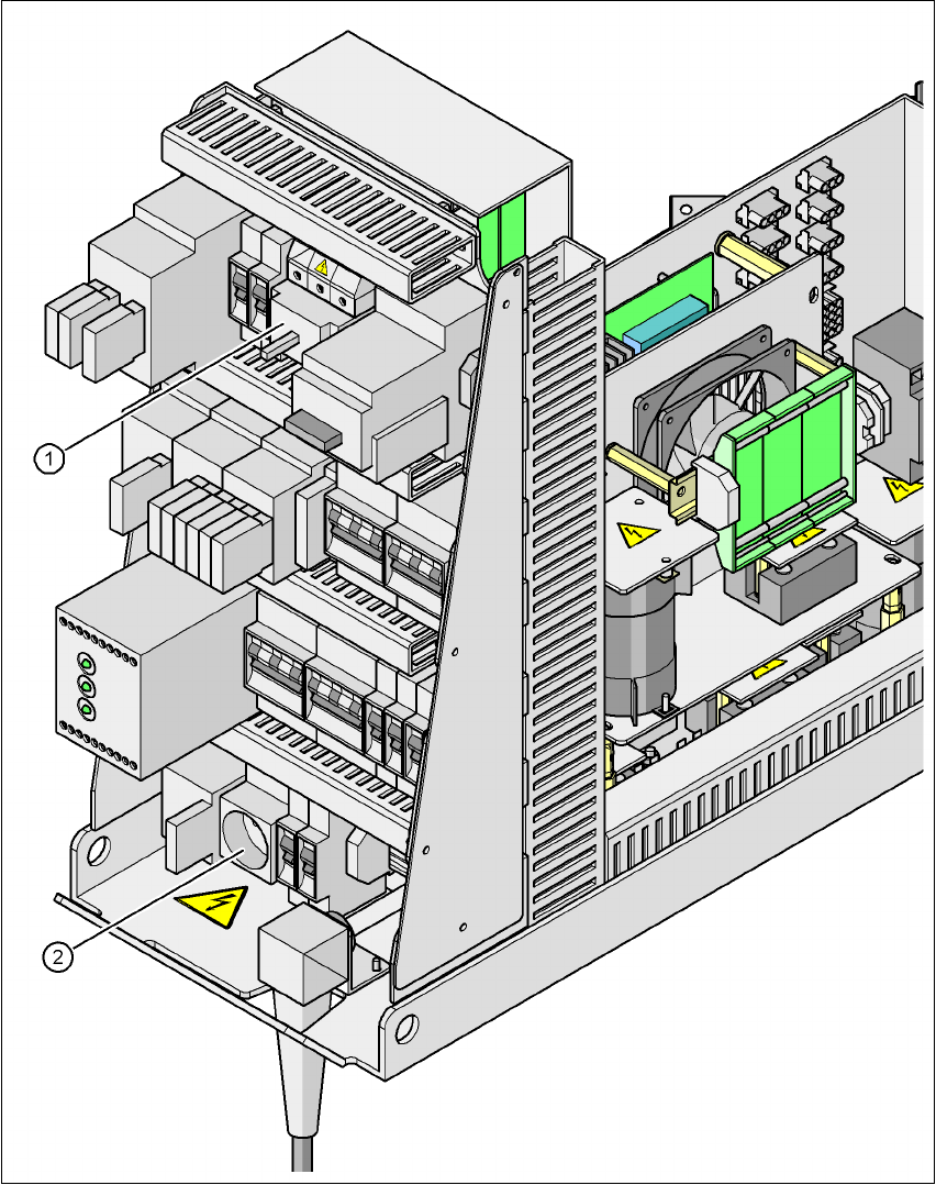
Fig. 2.9 - 1 Position of the power supply on the machine
2
WARNING
The placement system is supplied with 3 x 208 VAC, 3 x 230 VAC, 3 x 380 VAC, 3 x 400 VAC or
3 x 415 VAC ± 5 %, 50/60 Hz mains voltage. This means that some parts of the system carry po-
tentially lethal voltages - even when switched off at the main power switch. Incorrect handling of
the placement system can therefore result in death or severe injury or considerable damage to
equipment. 2
Æ Always follow the applicable accident prevention and DIN regulations (particularly DIN EN 60
204, part 1).
Æ The guard over the power supply unit must ONLY be opened by appropriately qualified and
trained personnel.
(1) Main power switch
User manual SIPLACE HF series 2 Operational safety
Software Version SR.50x.xx 01/2006 US Edition 2.9 Energy state of the machine after switching off at the main power switch
79
2
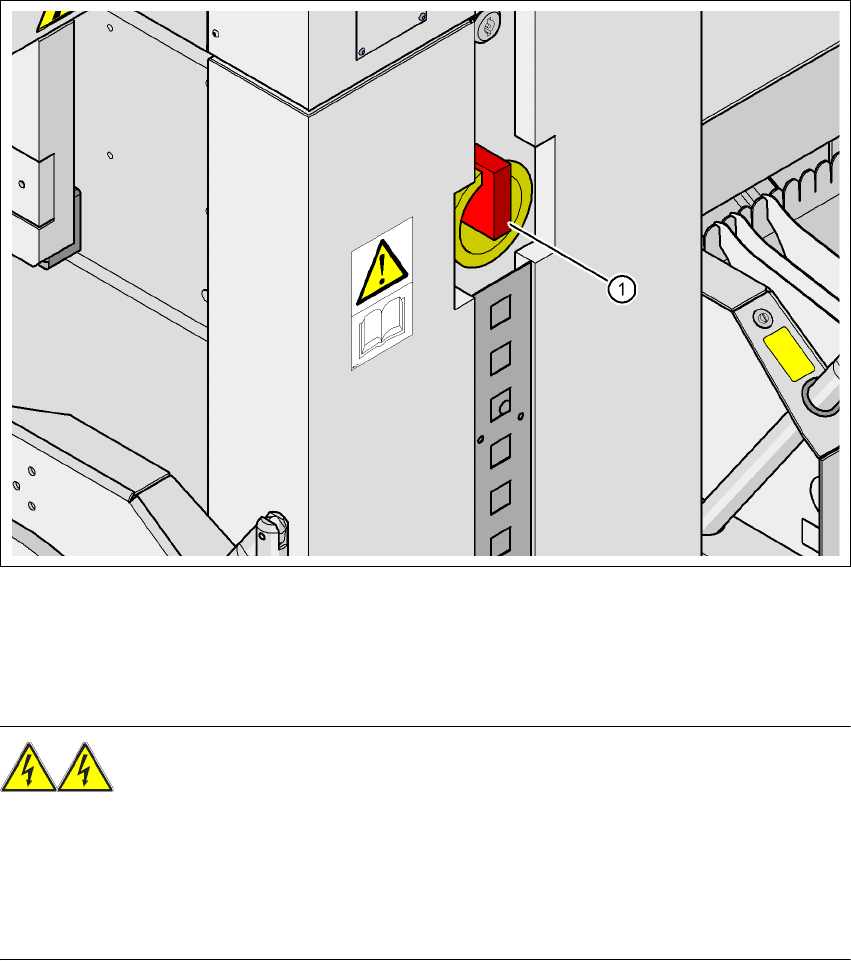
Fig. 2.9 - 2 Position of main power switch and service socket
2
(1) Main power switch
(2) Service socket
2 Operational safety User manual SIPLACE HF series
2.9 Energy state of the machine after switching off at the main power switch Software Version SR.50x.xx 01/2006 US Edition
80
2
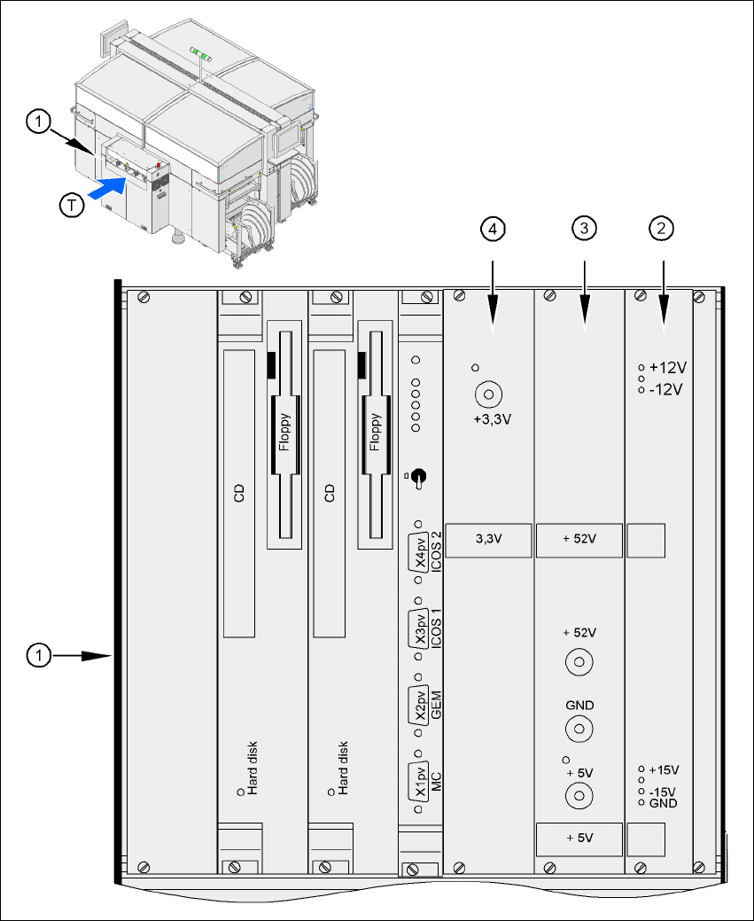
Fig. 2.9 - 3 Position of the computer unit
2
(1) Computer unit (top part)
(2) Power supply unit ± 12 V-/± 15 V-
(3) Power supply unit + 5 V-/+ 52 V-
(4) Power supply unit + 3.3 VDC
(T) Direction of PCB transport