00193922-03.pdf - 第82页
2 Operational safety User manual SIPLACE HF series 2.9 Energy state of the machine af ter switching off at t he main power switch Software Vers ion SR.50x.xx 01/2006 US E dition 82 2 Fig. 2.9 - 4 Power s upply unit, fron…
User manual SIPLACE HF series 2 Operational safety
Software Version SR.50x.xx 01/2006 US Edition 2.9 Energy state of the machine after switching off at the main power switch
81
2.9.1 Placement system switched off at the main switch, but still connected ...
WARNING
The following components still carry potentially lethal voltages even if the main power switch is
switched off:
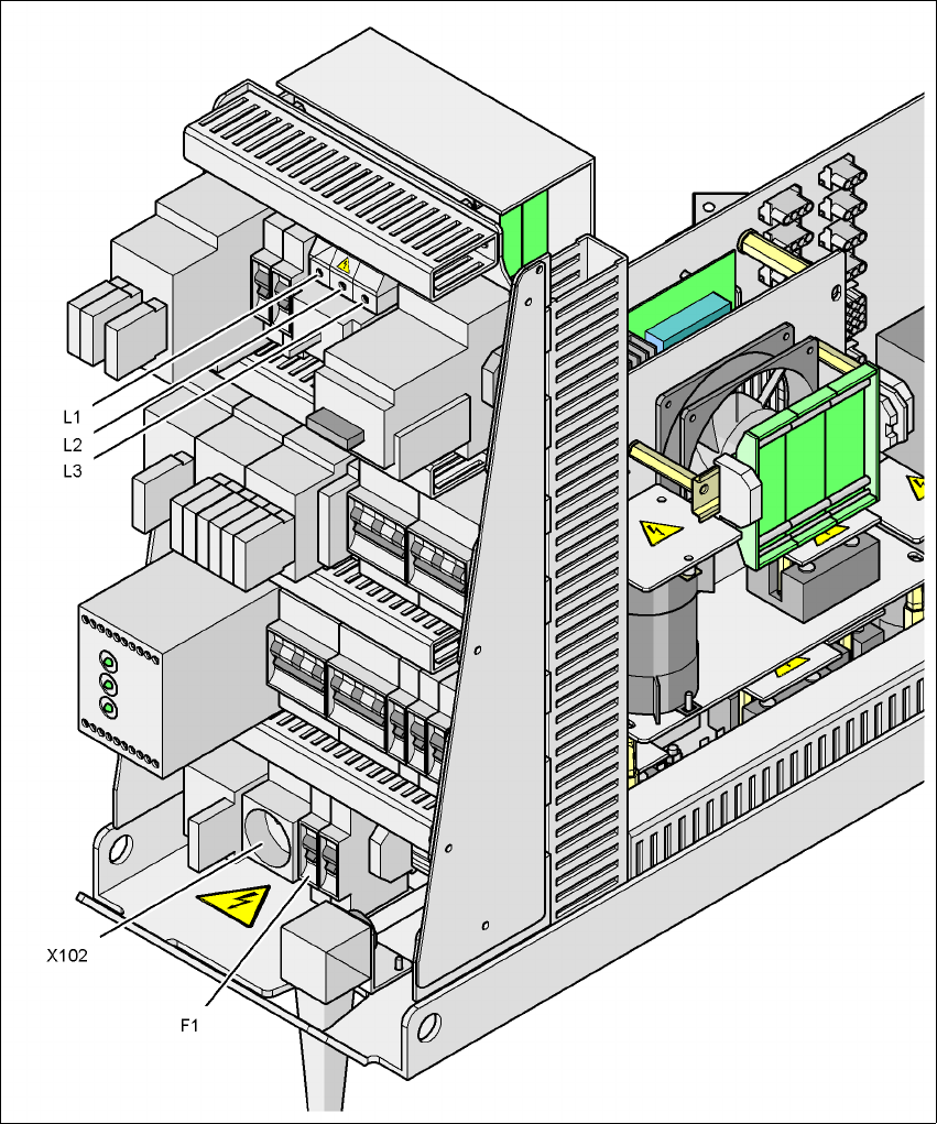
– Cable connecting terminals L1, L2, and L3 in the main power switch Q1 (see Fig. 2.9 - 4
)
– Service socket X102 (see Fig. 2.9 - 4
)
– Automatic circuit breaker F1 for the service socket (see Fig. 2.9 - 4
)
– Mains filter Z1 (see Fig. 2.9 - 4
)
– Terminal panel X100 for connecting the power supply cable
– The color of all individual wires, which still carry potentially lethal voltages even if the main
power switch is switched off, is brown.
– Axis unit
2 Operational safety User manual SIPLACE HF series
2.9 Energy state of the machine after switching off at the main power switch Software Version SR.50x.xx 01/2006 US Edition
82
2
Fig. 2.9 - 4 Power supply unit, front view
2
Q1 Main power switch
X102 Service socket
F1 Fuse for the service socket
User manual SIPLACE HF series 2 Operational safety
Software Version SR.50x.xx 01/2006 US Edition 2.9 Energy state of the machine after switching off at the main power switch
83
2
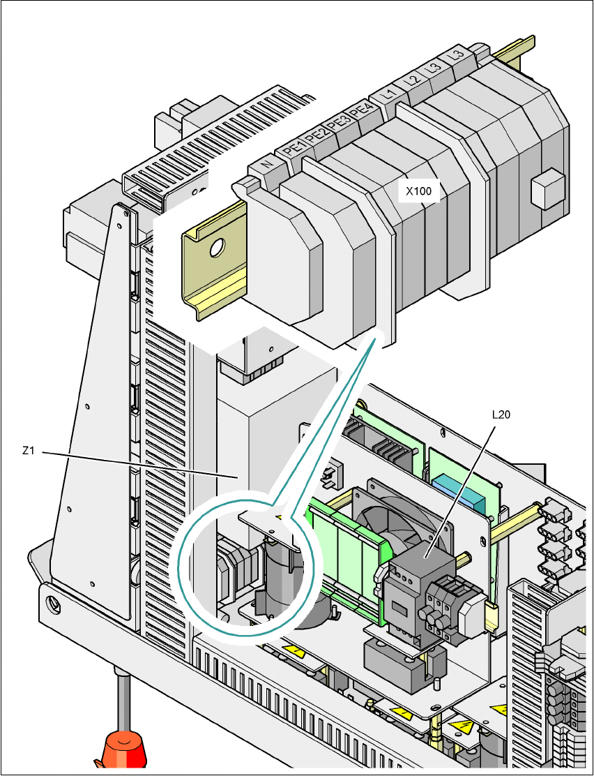
Fig. 2.9 - 5 Power supply unit, back view
2
X100 Cable connection terminal for the power supply cable
L20 Discharge reactor with fuses F21, F22 and F23
Z1 Line filter