00193922-03.pdf - 第83页
User manual SIPLAC E HF series 2 Operational safety Software Vers ion SR.50x.xx 01/2006 US Ed ition 2.9 Energy state of the machine af ter switching off at t he main power sw itch 83 2 Fig. 2.9 - 5 Power supply unit, bac…
2 Operational safety User manual SIPLACE HF series
2.9 Energy state of the machine after switching off at the main power switch Software Version SR.50x.xx 01/2006 US Edition
82
2
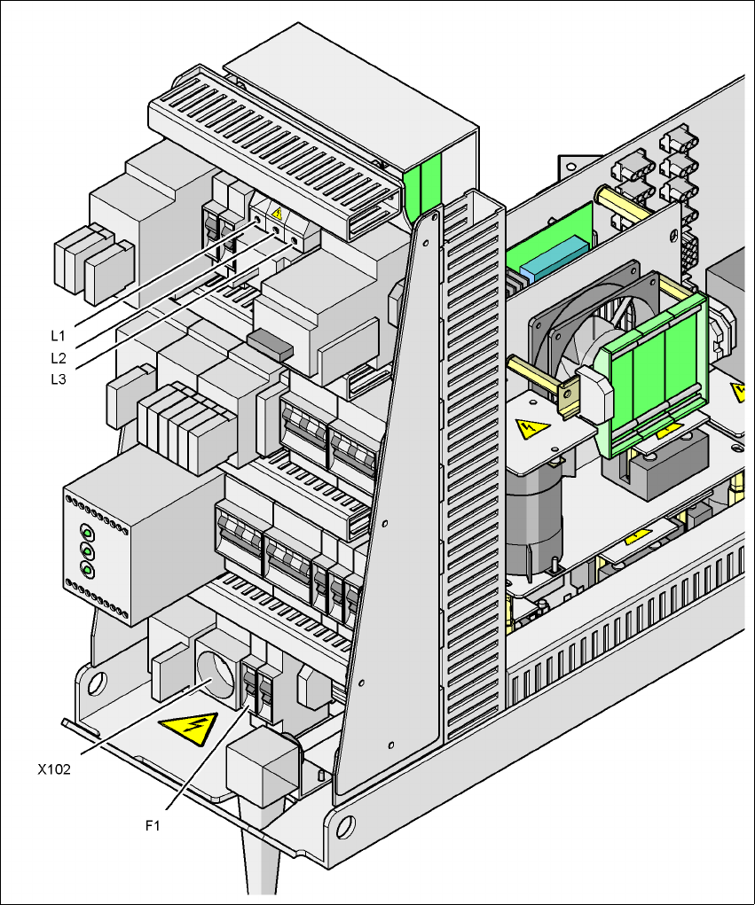
Fig. 2.9 - 4 Power supply unit, front view
2
Q1 Main power switch
X102 Service socket
F1 Fuse for the service socket
User manual SIPLACE HF series 2 Operational safety
Software Version SR.50x.xx 01/2006 US Edition 2.9 Energy state of the machine after switching off at the main power switch
83
2
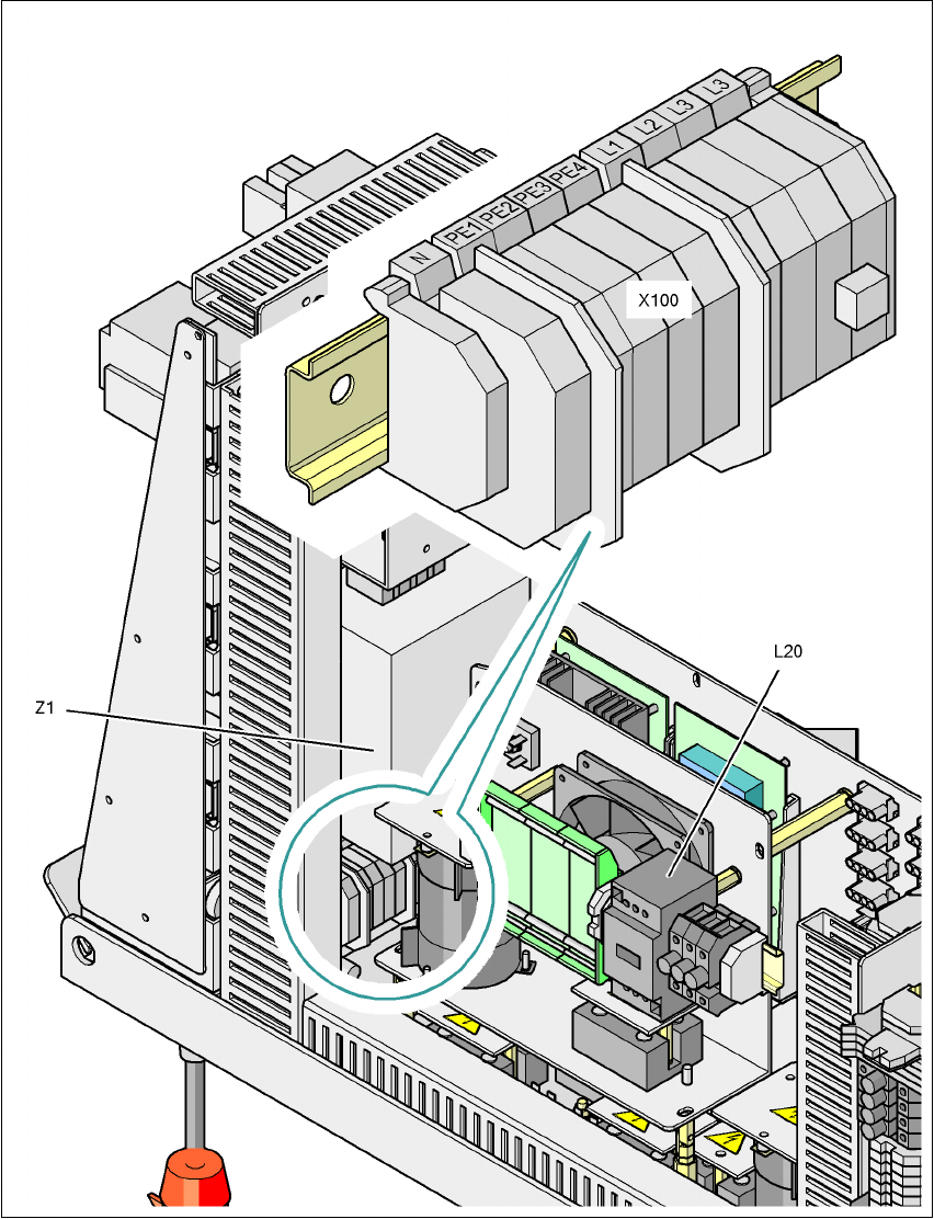
Fig. 2.9 - 5 Power supply unit, back view
2
X100 Cable connection terminal for the power supply cable
L20 Discharge reactor with fuses F21, F22 and F23
Z1 Line filter
2 Operational safety User manual SIPLACE HF series
2.9 Energy state of the machine after switching off at the main power switch Software Version SR.50x.xx 01/2006 US Edition
84
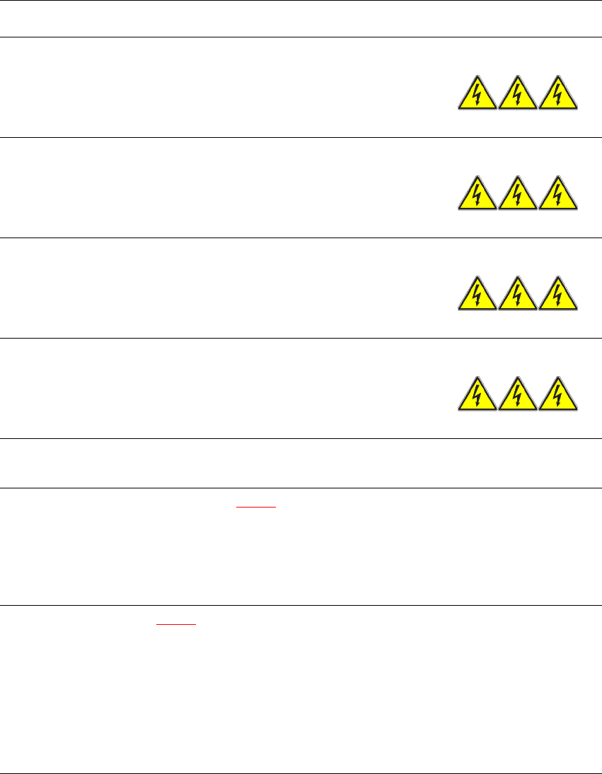
The following table specifies the voltages of modules when the automatic placement system is
switched off at the main switch, but still connected to the mains supply.
2
Module Voltage
Terminal panel X100
Line filter Z1
Terminals L1, L2, L3
3 x 208 VAC
3 x 230 VAC
3 x 380 VAC
3 x 400 VAC
3 x 415 VAC
Service socket X102
120 VAC
130 VAC
220 VAC
230 VAC
240 VAC
F1 automatic circuit breaker
120 VAC
130 VAC
220 VAC
230 VAC
240 VAC
Main switch Q1
Terminals L1, L2, L3
3 x 208 VAC
3 x 230 VAC
3 x 380 VAC
3 x 400 VAC
3 x 415 VAC
Main switch Q1
Terminals T1, T2, T3
0 VAC
Power supply unit (see item 5 in Fig. 2.7 - 2
)
Test socket X11
GND X12
Test socket X13_1
Test socket X13_4
GND X13_7
< 10 VDC
< 10 VDC
< 10 VDC
Computer unit (see Fig. 2.9 - 3
)
Test socket + 12 VDC
Test socket - 12 VDC
Test socket + 15 VDC
Test socket -15 VDC
Test socket + 5 VDC
Test socket + 52 VDC
Test socket + 3.3 VDC
GND
0 VDC
0 VDC
0 VDC
0 VDC
0 VDC
0 VDC
0 VDC