00193922-03.pdf - 第96页
3 Technical data User manual SIPLACE HF series 3.2 Performance dat a for the mac hines Software Vers ion SR.50x.xx 01/2006 US Ed ition 96 3.2 Performanc e dat a for the machine s T ypes of placemen t head SIPLACE T winHe…
User manual SIPLACE HF series 3 Technical data
Software Version SR.50x.xx 01/2006 US Edition 3.1 Description of the machine
95
3
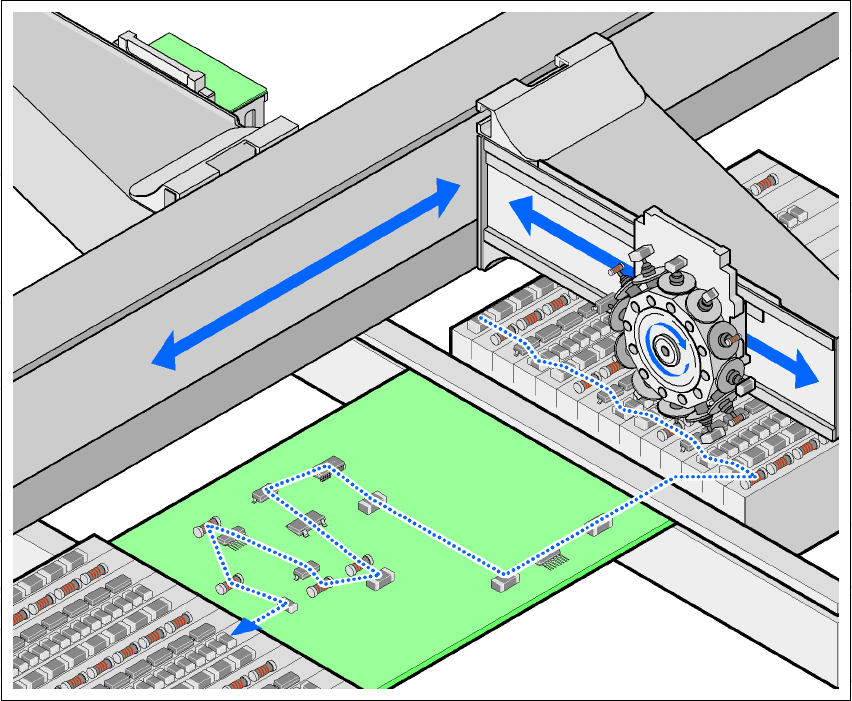
Fig. 3.1 - 2 Placement principle using the Collect&Place method
3
The following options are available to extend the machine's functionality:
– Additional component trolleys increase machine utilization since set-up times can be reduced
by carrying out preliminary set-up off the machine.
– The dual conveyor also increases machine utilization by eliminating non-productive PCB
transport times.
– Automatic nozzle changers speed up and optimize the nozzle configuration process.
– PCB barcode scanners allow the production set-up to be changed over when triggered by a
new product.
– Component barcode scanners optimize the set-up and refill checks.
– Large and sensitive components can be supplied in trays in add-on matrix tray changers.
– The productivity lift implements the concept of parallel placement, and thus improves the ratio
between productive and non-productive times.

3 Technical data User manual SIPLACE HF series
3.2 Performance data for the machines Software Version SR.50x.xx 01/2006 US Edition
96
3.2 Performance data for the machines
Types of placement head SIPLACE TwinHead (TH)
6-segment Collect&Place head (C&P6)
12-segment Collect&Place head (C&P12)
Number of gantries HF: 2
HF/3: 3
Placement rate (benchmark)
HF
HF/3
Placement area 1 Placement area 2
Gantry 1 Gantry 3
C&P12 / C&P12 28,000 comp./h
C&P12 / C&P6 23,300 comp./h
C&P6 C&P6 18,600 comp./h
C&P12 TH 17,700 comp./h
C&P6 TH 13,000 comp./h
TH TH 7,400 comp./h
Placement area 1 Placement area 2
Gantry 1 / Gantry 4 Gantry 3
C&P12 / C&P12 C&P12 40,400 comp./h
C&P12 / C&P12 C&P6 35,700 comp./h
C&P12 / C&P12 TH 30,100 comp./h
C&P12 / C&P6 C&P6 29,600 comp./h
C&P12 / C&P6 TH 24,000 comp./h
C&P6 / C&P12 C&P6 29,600 comp./h
C&P6 / C&P12 TH 24,000 comp./h
C&P6 / C&P6 C&P6 27,600 comp./h
C&P6 / C&P6 TH 22,000 comp./h
Component range 0.6 x 0.3 mm² (0201) to 85 x 85 mm² / 125 x 10 mm²,
up to 200 x 125 mm² (with restrictions)
Component height C&P12: 6 mm
C&P6: 8.5 mm
TH: 25 mm (The height reduces to 18.3 mm when a multi-
color camera is installed.)
Placement accuracy C&P12:
Standard CO camera (24 x 24):
± 45 µm (3 σ), ± 60 µm (4 σ)
DCA vision camera:
± 41 µm (3 σ), ± 55 µm (4 σ)
C&P6:
Standard CO camera (39 x 39):
± 45 µm (3 σ), ± 60 µm (4 σ)
DCA vision camera:
± 41 µm (3 σ), ± 55 µm (4 σ)
TH:
CO camera, type 22 (50 x 40):
± 26 µm (3 σ) ± 35 µm (4 σ)
CO camera, type 20 (8 x 8):
± 22 µm (3 σ), ± 30 µm (4 σ)
Angular accuracy C&P12: ± 0.5° (3 σ)± 0.7°(4 σ)
C&P6: ± 0.2° (3 σ)± 0.3°(4 σ)
TH: ± 0.05° (3 σ) ± 0.07°(4 σ)

User manual SIPLACE HF series 3 Technical data
Software Version SR.50x.xx 01/2006 US Edition 3.3 Ratings of the placement system
97
3.3 Ratings of the placement system
3
Component feeding 4 component trolleys with tape reel holders and integral
waste containers
15 slots, 30 mm wide, per component trolley or up to 2
matrix tray changers, rather than component trolleys
(HF/3: 1 MTC)
Feeder module types Tapes, bulk cases, stick magazines, application-specific
OEM feeder modules, surftape feeder modules (8, 12,
16 mm), waffle-pack trays
Feeding capacity 180 tracks, width 8 mm (60 S feeders, 3 x 8 mm)
120 tracks, width 8 mm (60 S feeders, 2 x 8 mm)
60 tracks, width 12 or 16 mm (60 S feeders, 12/16 mm)
40 tracks, width 24 or 32 mm (40 S feeders, 24/32 mm)
28 tracks, width 44 mm (28 S feeders, 44 mm)
24 tracks, width 56 mm (24 S feeders, 56 mm)
20 tracks, width 72 mm (20 S feeders, 72 mm)
16 tracks, width 88 mm (16 S feeders, 88 mm)
PCB format (LxW)
Single conveyor
50 x 50 mm² to 450 x 508 mm²
50 x 80 mm² to 610 x 508 mm² ("Long board" option)
Dual conveyor
50 x 50 mm² to 450 x 250 mm²
50 x 80 mm² to 610 x 250 mm² ("Long board" option)
Dual conveyor in Single conveyor mode
50 x 50 mm² to 450 x 450 mm²
50 x 80 mm² to 610 x 450 mm² ("Long board" option)
PCB thickness 0.3 to 4.5 mm (thicker PCBs available on request)
Electrical ratings
Supply voltage 3 x 208 VAC ± 5 %; 50/60 Hz (for the U.S.A. version)
3 x 230 VAC ± 5 %; 50/60 Hz
3 x 380 VAC ± 5 %; 50/60 Hz
3 x 400 VAC ± 5 %; 50/60 Hz (Europe)
3 x 415 VAC ± 5 %; 50/60 Hz
Fuses 3 x 32 A (3 x 208 VAC)
3 x 32 A (3 x 230 VAC)
3 x 16 A (3 x 380 VAC)
3 x 16 A (3 x 400 VAC)
3 x 16 A (3 x 415 VAC)
Nominal apparent power 3.5 kVA (HF/3)
3.3 kVA (HF)