00193922-03.pdf - 第98页
3 Technical data User manual SIPLACE HF series 3.3 Ratings of the placement system Software Version SR.50x.xx 01/2006 US Edition 98 Rat ed cur rent consump tion 8.9 A / 3 x 400 VAC ( H F/3 ) 8.2 A / 3 x 400 VAC (HF) Powe…

User manual SIPLACE HF series 3 Technical data
Software Version SR.50x.xx 01/2006 US Edition 3.3 Ratings of the placement system
97
3.3 Ratings of the placement system
3
Component feeding 4 component trolleys with tape reel holders and integral
waste containers
15 slots, 30 mm wide, per component trolley or up to 2
matrix tray changers, rather than component trolleys
(HF/3: 1 MTC)
Feeder module types Tapes, bulk cases, stick magazines, application-specific
OEM feeder modules, surftape feeder modules (8, 12,
16 mm), waffle-pack trays
Feeding capacity 180 tracks, width 8 mm (60 S feeders, 3 x 8 mm)
120 tracks, width 8 mm (60 S feeders, 2 x 8 mm)
60 tracks, width 12 or 16 mm (60 S feeders, 12/16 mm)
40 tracks, width 24 or 32 mm (40 S feeders, 24/32 mm)
28 tracks, width 44 mm (28 S feeders, 44 mm)
24 tracks, width 56 mm (24 S feeders, 56 mm)
20 tracks, width 72 mm (20 S feeders, 72 mm)
16 tracks, width 88 mm (16 S feeders, 88 mm)
PCB format (LxW)
Single conveyor
50 x 50 mm² to 450 x 508 mm²
50 x 80 mm² to 610 x 508 mm² ("Long board" option)
Dual conveyor
50 x 50 mm² to 450 x 250 mm²
50 x 80 mm² to 610 x 250 mm² ("Long board" option)
Dual conveyor in Single conveyor mode
50 x 50 mm² to 450 x 450 mm²
50 x 80 mm² to 610 x 450 mm² ("Long board" option)
PCB thickness 0.3 to 4.5 mm (thicker PCBs available on request)
Electrical ratings
Supply voltage 3 x 208 VAC ± 5 %; 50/60 Hz (for the U.S.A. version)
3 x 230 VAC ± 5 %; 50/60 Hz
3 x 380 VAC ± 5 %; 50/60 Hz
3 x 400 VAC ± 5 %; 50/60 Hz (Europe)
3 x 415 VAC ± 5 %; 50/60 Hz
Fuses 3 x 32 A (3 x 208 VAC)
3 x 32 A (3 x 230 VAC)
3 x 16 A (3 x 380 VAC)
3 x 16 A (3 x 400 VAC)
3 x 16 A (3 x 415 VAC)
Nominal apparent power 3.5 kVA (HF/3)
3.3 kVA (HF)

3 Technical data User manual SIPLACE HF series
3.3 Ratings of the placement system Software Version SR.50x.xx 01/2006 US Edition
98
Rated current consumption 8.9 A / 3 x 400 VAC (HF/3)
8.2 A / 3 x 400 VAC (HF)
Power failure Max. 20 msec
Compressed air supply
Compressed air pressure
p
min
p
max
0.5 MPa = 5.0 bar
1.0 MPa = 10 bar
Compressed air connection 3/4" thread with 1/2" hose connection
Compressed air consumption with
4 tape cutters and in relation to the
placement head configuration
HF placement machine
C&P / TH 350 st. l/min
C&P / C&P 450 st. l/min
TH / TH 300 st. l/min
HF/3 placement machine
C&P / C&P / TH 550 st. l/min
C&P / C&P / C&P 700 st. l/min
Operating pressure 0.48 MPa ± 0.025 MPa (4.8 bar ± 0.25 bar)
Compressed air specification
Maximum particle size by density, based on ISO/DIS 8573-1 (class 1)
Particle size 0.1 µm
Particle density 0.1 mg/m³
Maximum oil content (class 1) Particle density 0.01 mg/m³
Pressure dewpoint (class 4) Dewpoint +3°
Noise emissions
Max. noise emissions 74 dB (A)
Permitted environmental factors
Room temperature Between 15°C and 35°C
Atmospheric humidity 30 to 75%
(but no higher than 45% on average in order to prevent any
possibility of condensation on the machine).
User manual SIPLACE HF series 3 Technical data
Software Version SR.50x.xx 01/2006 US Edition 3.4 Dimensions and weight of the placement machines
99
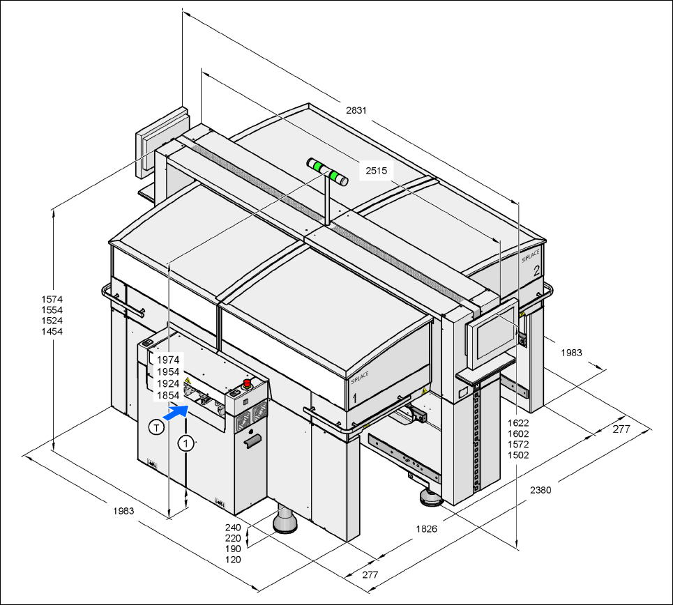
3.4 Dimensions and weight of the placement machines
3.4.1 Dimensions of the HF placement machine
3
3
3
3
3
Fig. 3.4 - 1 Dimensions of the HF placement machine (basic machine) in millimeters