X7056_Operating manual_en.pdf - 第101页
Installation First use 101 Inspection system X7056 | Operating manual | Version 3.1 Rev.006| 2016-01-06 | 30.009.1930a Perform the following work steps: Check that the Interlock connecti ons are allocated, see „Inter- …
Installation
First use
100
Inspection system X7056 | Operating manual |
Version 3.1 Rev.006| 2016-01-06 | 30.009.1930a
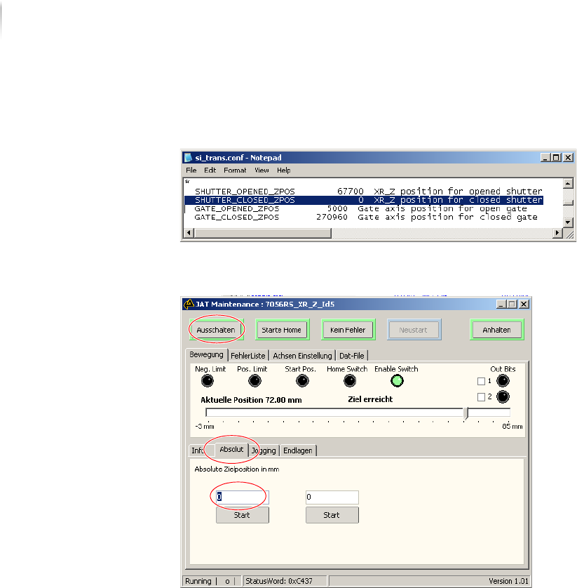
10.Read the value in parameter SHUTTER_CLOSED_ZPOS.
The value gives the position of the closed shutter in µm.
11.Enter the value from si_trans.conf in mm in JAT MAINTENANCE
Tool in the tab Movement - Absolute.
12.Confirm with Enter; click the button START.
The shutter is closed.
The Interlock connections in the program XRAYCLOSEDTUBE-
C
ONTROL are closed.
The shutter functioning is checked
Checking the Interlock linkage
Precondition: The white ON button does not light up?
Installation
First use
101
Inspection system X7056 | Operating manual |
Version 3.1 Rev.006| 2016-01-06 | 30.009.1930a
Perform the following work steps:
Check that the Interlock connections are allocated, see „Inter-
lock linkage“ (Page 49).
The Interlock connections are allocated.
The white ON button lights up.
? The white ON button does not light up?
Devices connected by the Interlock are in the STOP mode
End the STOP mode of the connected devices.
The Interlock linkage is checked.
Checking the SMEMA protocol
After the inspection system is switched on, check the SMEMA/SV70
protocols, see .
Precondition: The inspection system is switched on.
The external components are switched on.
Checking
communication
with SMEMA N-
1A
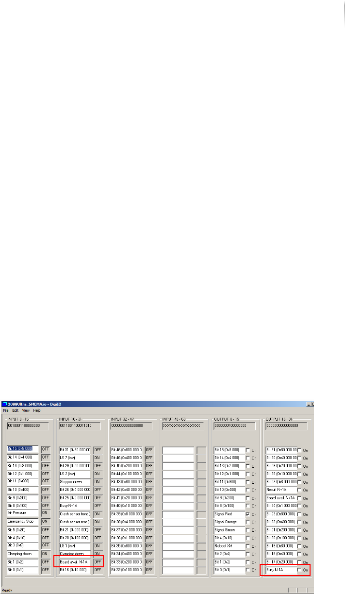
Perform the following work steps:
1. Place a PCB in the transport conveyor of the external compo--
nent N-1A.
2. Click S
TART > MAINTENANCE PROGRAM > DIGIIO.
3. Set the output signal N -1A Busy to ON.
The input signal N-1A Board Available changes to ON.
The transport conveyor of the external component starts.
4. Remove the PCB from the transport conveyor of the external
component.
The input signal N-1A Board Available changes to OFF.
Installation
First use
102
Inspection system X7056 | Operating manual |
Version 3.1 Rev.006| 2016-01-06 | 30.009.1930a
5. Set the output signal N-1A Busy to OFF.
The transport conveyor of the external component stops.
Communication with SMEMA N-1A is checked.
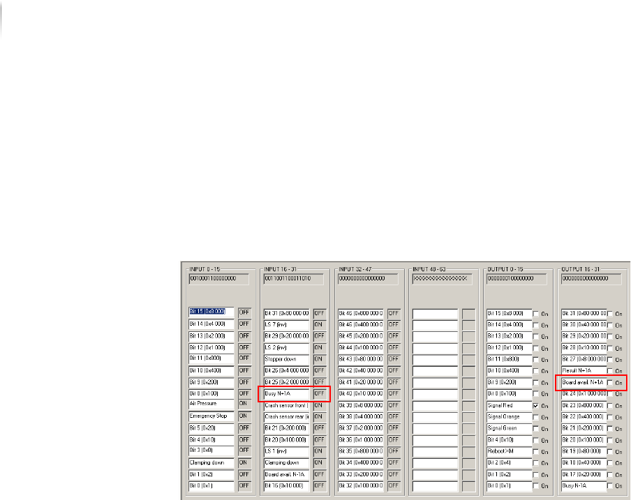
Checking
communication
with SMEMA
N+1A
Perform the following work steps:
1. Click S
TART > MAINTENANCE PROGRAM > DIGIIO.
The input signal N+1A Busy is at ON.
2. Set the output signal N+1A Board Available to
ON.
The transport conveyor of the external component starts.
3. Place a PCB in the transport conveyor of the external compo--
nent.
4. Set the output signal N+1A Board Available to
OFF.
The input signal N+1A Busy changes to OFF.
Communication with SMEMA N+1A is checked.
The SMEMA protocol is checked.