X7056_Operating manual_en.pdf - 第103页
Installation First use 103 Inspection system X7056 | Operating manual | Version 3.1 Rev.006| 2016-01-06 | 30.009.1930a Checking the SV70 protocol Checking communication with SV70 N-1A Perform the following work steps: 1.…
Installation
First use
102
Inspection system X7056 | Operating manual |
Version 3.1 Rev.006| 2016-01-06 | 30.009.1930a
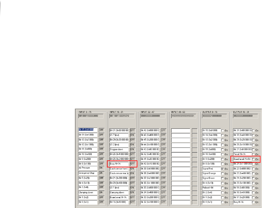
5. Set the output signal N-1A Busy to OFF.
The transport conveyor of the external component stops.
Communication with SMEMA N-1A is checked.
Checking
communication
with SMEMA
N+1A
Perform the following work steps:
1. Click S
TART > MAINTENANCE PROGRAM > DIGIIO.
The input signal N+1A Busy is at ON.
2. Set the output signal N+1A Board Available to
ON.
The transport conveyor of the external component starts.
3. Place a PCB in the transport conveyor of the external compo--
nent.
4. Set the output signal N+1A Board Available to
OFF.
The input signal N+1A Busy changes to OFF.
Communication with SMEMA N+1A is checked.
The SMEMA protocol is checked.
Installation
First use
103
Inspection system X7056 | Operating manual |
Version 3.1 Rev.006| 2016-01-06 | 30.009.1930a
Checking the SV70 protocol
Checking
communication
with SV70 N-1A
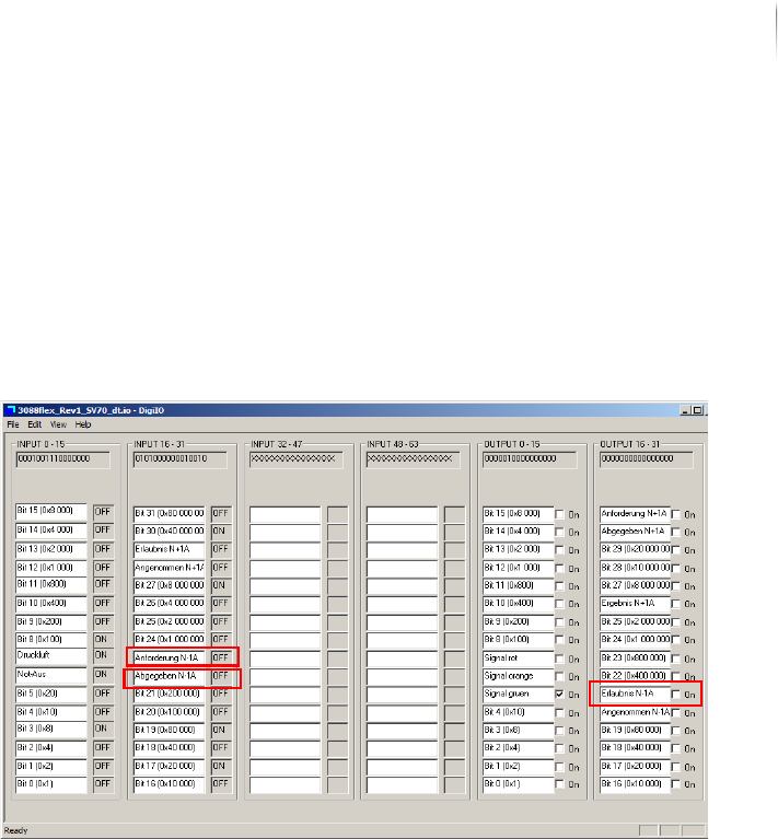
Perform the following work steps:
1. Place a PCB in the transport conveyor of the external compo--
nent N-1A.
2. Click S
TART > MAINTENANCE PROGRAM > DIGIIO.
The input signal N-1A request is at ON.
3. Set the output signal N-1A Permission to
ON.
The transport conveyor of the external component starts.
4. Remove the PCB from the transport conveyor of the external
component.
The input signal N-1A Request changes to OFF and the input
signal N-1A Released changes to
ON.
5. Set the output signal N-1A Accepted to
ON and the output signal
N-1A Permission to
OFF.
The transport conveyor of the external component stops.
Communication with SV70 N-1A is checked.
Installation
First use
104
Inspection system X7056 | Operating manual |
Version 3.1 Rev.006| 2016-01-06 | 30.009.1930a
Checking
communication
with SV70
N+1A
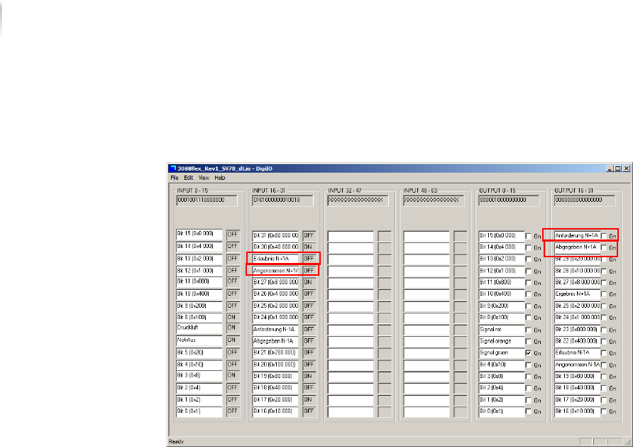
Perform the following work steps:
1. Click S
TART > MAINTENANCE PROGRAM > DIGIIO.
2. Set the output signal N+1A Request to
ON.
The input signal N+1A permission changes to ON.
The transport conveyor of the external component starts.
3. Remove the PCB from the transport conveyor of the external
component.
4. Set the output signal N+1A Released to
ON and the output
signal N+1A Request to
OFF.
The input signal N+1A accepted changes to ON and the input
signal N+1A permission changes to OFF.
Communication with SV70 N+1A is checked.
The SV70 protocol is checked.
Checking the PCB transport
After the protocols are checked, check the function of the auto--
matic PCB transport.
Precondition: The SMEMA/SV70 protocols are checked.
Perform the following work steps:
1. Start the Viscom software, see „Starting the Viscom software“
(Page 155).
2. Select an inspection plan, see „Choosing an inspection
program“ (Page 156).