X7056_Operating manual_en.pdf - 第117页
Software Automatic mode 117 Inspection system X7056 | Operating manual | Version 3.1 Rev.006| 2016-01-06 | 30.009.1930a User interface The user interface consists of si x file tabs, which display informa- tion about defe…
Software
Automatic mode
116
Inspection system X7056 | Operating manual |
Version 3.1 Rev.006| 2016-01-06 | 30.009.1930a
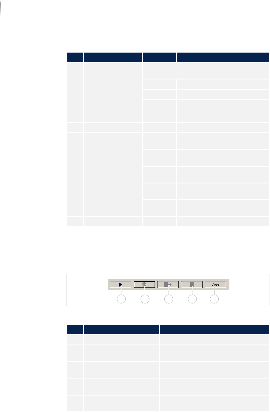
Operation bar
The operation bar contains the following buttons to control the
inspection operation.
Operation bar
Description of the fields
No. Name Value Description
1 PROGRESS BAR Displays the progress of the current inspec-
tion.
Time - not yet available -
Window - not yet available -
Positions Shows the progress of the
inspection referenced to the
positions to be inspected.
2 INSPECTION TRACK - Not yet allocated
3 INSPECTION DURA-
TION
Analysis
time
Displays the pure analysis time
without PCB handling.
Cycle time Displays the pure analysis time
without PCB handling.
Process
time
Not yet allocated
Operating
time
Displays the operating time of
the inspection system.
Running
time
Displays the running time of the
inspection operation.
4 INFO - Not yet allocated
Description of the buttons
No. Name Description
1 START PCB INSPECTION Starts the inspection operation.
2 STOP PCB INSPECTION Interrupts the inspection operation
(default: inactive; can be configured).
3 END INSPECTION OPERA-
TION WITH OUTFEED
Ends the inspection and outfeeds the
PCB
4 END INSPECTION OPERA-
TION
Ends the inspection without outfeeding
the PCB.
5 CLOSE Closes the automatic operation
window.
1 2 43 5
Software
Automatic mode
117
Inspection system X7056 | Operating manual |
Version 3.1 Rev.006| 2016-01-06 | 30.009.1930a
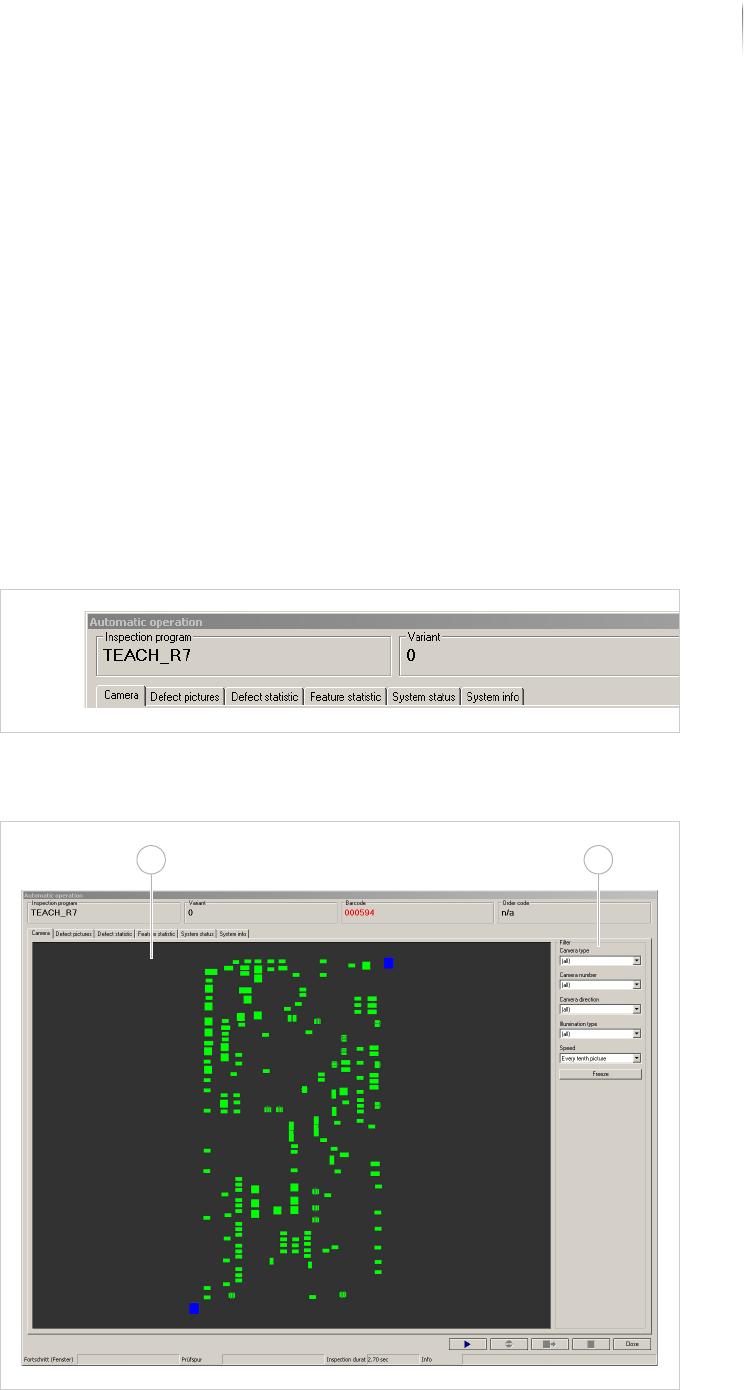
User interface
The user interface consists of six file tabs, which display informa-
tion about defect images, statistics of the running inspection as
well as the system state.
The following elements are described:
C
AMERA (Page 117)
D
EFECT IMAGES (Page 120)
D
EFECT STATISTICS (Page 123)
F
EATURE STATISTIC (Page 129)
S
YSTEM STATUS (Page 132)
S
YSTEM INFO (Page 134)
Overview
The individual file tabs of the user interface and their settings are
explained in the following.
User interface file tabs
Camera
This file tab contains the fields:
File tab CAMERA IMAGE
21
Software
Automatic mode
118
Inspection system X7056 | Operating manual |
Version 3.1 Rev.006| 2016-01-06 | 30.009.1930a
The display of the captured camera images can be set with the
field F
ILTER. The selection choices depend on how the inspection
system is equipped and configured.
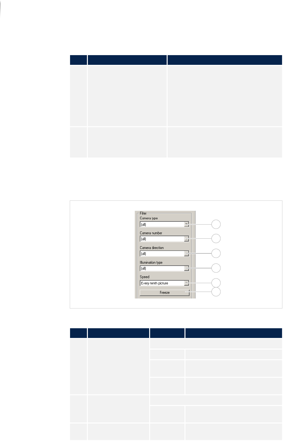
Field FILTER
Description of the fields
No. Name Description
1 CAMERA Displays the current captured live
image during the inspection.
If the inspection is ended, the PCB
overview image is displayed (default:
inactive; can be configured).
To enlarge the camera image, click on
the camera image with the right
mouse.
2 FILTER The display of the captured camera
images can be set (default: inactive;
can be configured). See „Field F
ILTER“
(Page 118)
Description of the field "Filter"
No. Name Value Description
1 CAMERA TYPE Selects the camera type.
All Selects all available cameras.
CAM_ORT
H_0
Selects the orthogonal camera.
CAM_ANGL
_1...
Selects the angled camera.
2 CAMERA NUMBER Selects the camera number.
All Selects all available camera
numbers.
0-... Selects a specific camera
number.
2
1
3
4
5
6