X7056_Operating manual_en.pdf - 第233页
Decommissioning Take the inspection system out of op eration 233 Inspection system X7056 | Operating manual | Version 3.1 Rev.006| 2016-01-06 | 30.009.1930a Removing the signal lamps Perform the following work steps: 1. …
Decommissioning
Take the inspection system out of operation
232
Inspection system X7056 | Operating manual |
Version 3.1 Rev.006| 2016-01-06 | 30.009.1930a
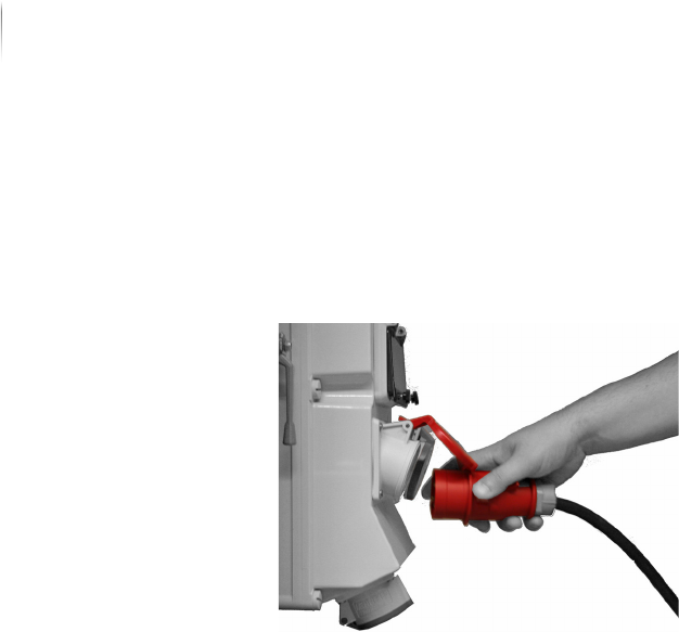
Disconnecting the Power Supply
Perform the following work steps:
Disconnect the inspection system from the main electrical
power supply.
The power supply is disconnected.
Disconnecting the SMEMA/SV70 interfaces
Perform the following work steps:
Disconnect the SMEMA/SV70 connections to the adjacent
devices.
The SMEMA/SV70 interfaces are disconnected.
Disconnecting the Interlock connections
Perform the following work steps:
Disconnect the Interlock connections to the adjacent devices.
The Interlock connections are disconnected.
Decommissioning
Take the inspection system out of operation
233
Inspection system X7056 | Operating manual |
Version 3.1 Rev.006| 2016-01-06 | 30.009.1930a
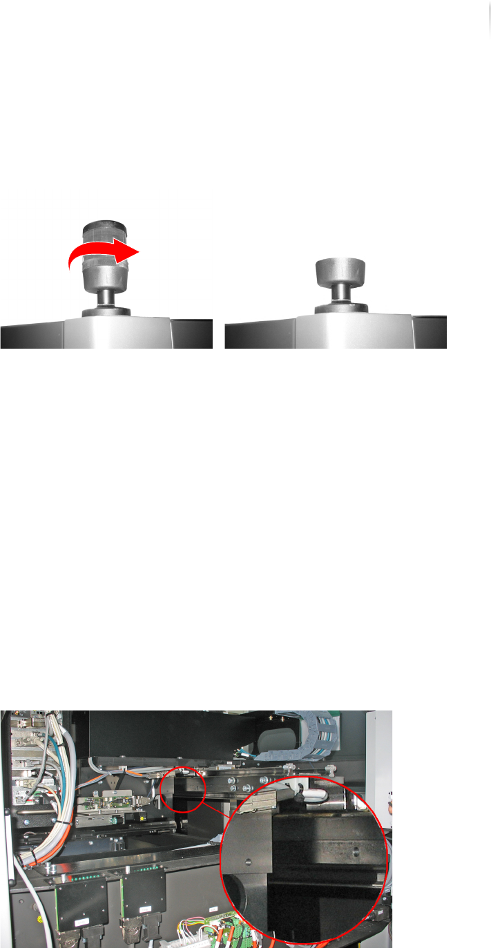
Removing the signal lamps
Perform the following work steps:
1. Unscrew the light elements from the signal lamps.
2. Place the light elements in a shipping carton.
Completed, continue ...
Attaching the AOI transportation safety devices
Precondition: Three transport locks are available.
The inspection system is switched off.
Required: 3 x Allen screws M6
7 x Allen screws M8
Allen (hex) keys (5 and 6 mm)
Attaching the
AOI camera
head transpor-
tation safety
devices
Perform the following work steps:
1. Open the front lift door.
The drill holes for the upper transport lock of the AOI area are
below the camera head and on the Y-axis.
Decommissioning
Take the inspection system out of operation
234
Inspection system X7056 | Operating manual |
Version 3.1 Rev.006| 2016-01-06 | 30.009.1930a
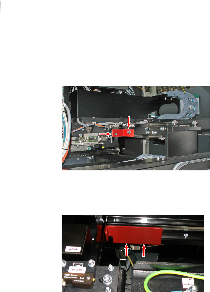
2. Move the image acquisition unit to the front in such a way that
the borings on the axis line up with the borings for the trans-
portation safety device.
3. Screw the Allen screw (M6) completely into the drill hole below
the camera head.
4. Screw the Allen screw (M 8) completely into the drill hole on
the Y-axis.
Completed, continue ...
Attaching the
AOI transport
track transpor-
tation safety
device
Perform the following work steps:
1. Move the AOI transport track completely to the right.
2. Fasten the lower lock with two Allen screws (M6).
Completed, continue ...
The AOI transportation safety devices are attached.