X7056_Operating manual_en.pdf - 第36页
Product description Operation and display elements 36 Inspection system X7056 | Operating manual | Version 3.1 Rev.006| 2016-01-06 | 30.009.1930a Additional radiation signal colum n (optional) Displays the generator oper…
Product description
Operation and display elements
35
Inspection system X7056 | Operating manual |
Version 3.1 Rev.006| 2016-01-06 | 30.009.1930a
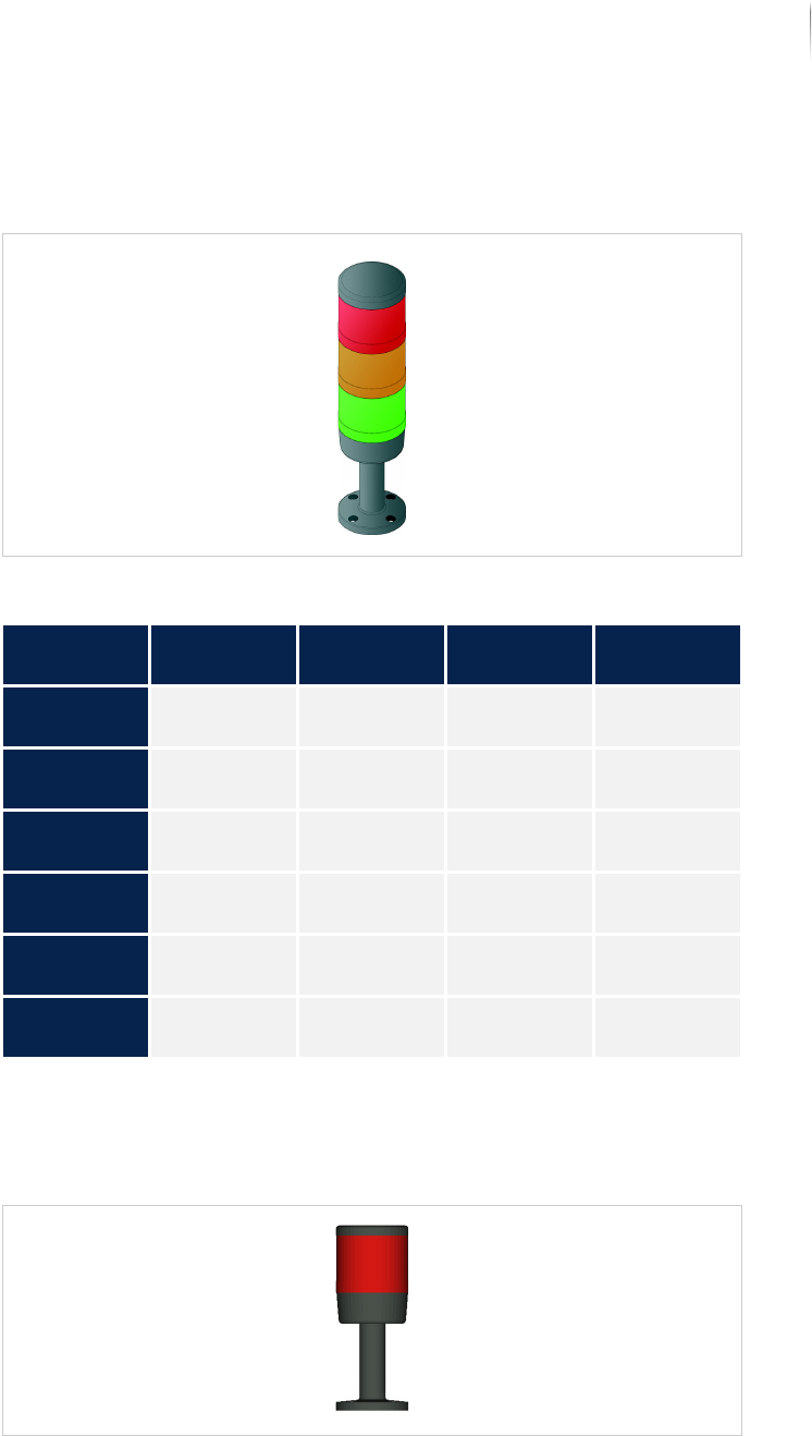
Signal lamp
Indicates the operating state of the inspection system and warns
the operator of malfunctions.
Signal lamp
X-ray signal
lamp
The red light element indicates radiation operation; optionally, an
additional orange light element displays the generator operation of
the inspection system.
X-ray signal lamp
Configuration of the signal lamp
Type of oper--
ation
Green Orange Red Horn
Continuous
operation
Lit - - -
Setup opera-
tion
- Lit - -
Manual oper--
ation
- Lit - -
No printed
circuit board
Lit Lit - Horn beeps
at intervals
Too long
without PCB
Lit Lit - Horn beeps
continuously
Malfunction: - - Blinks Horn beeps
continuously
Product description
Operation and display elements
36
Inspection system X7056 | Operating manual |
Version 3.1 Rev.006| 2016-01-06 | 30.009.1930a
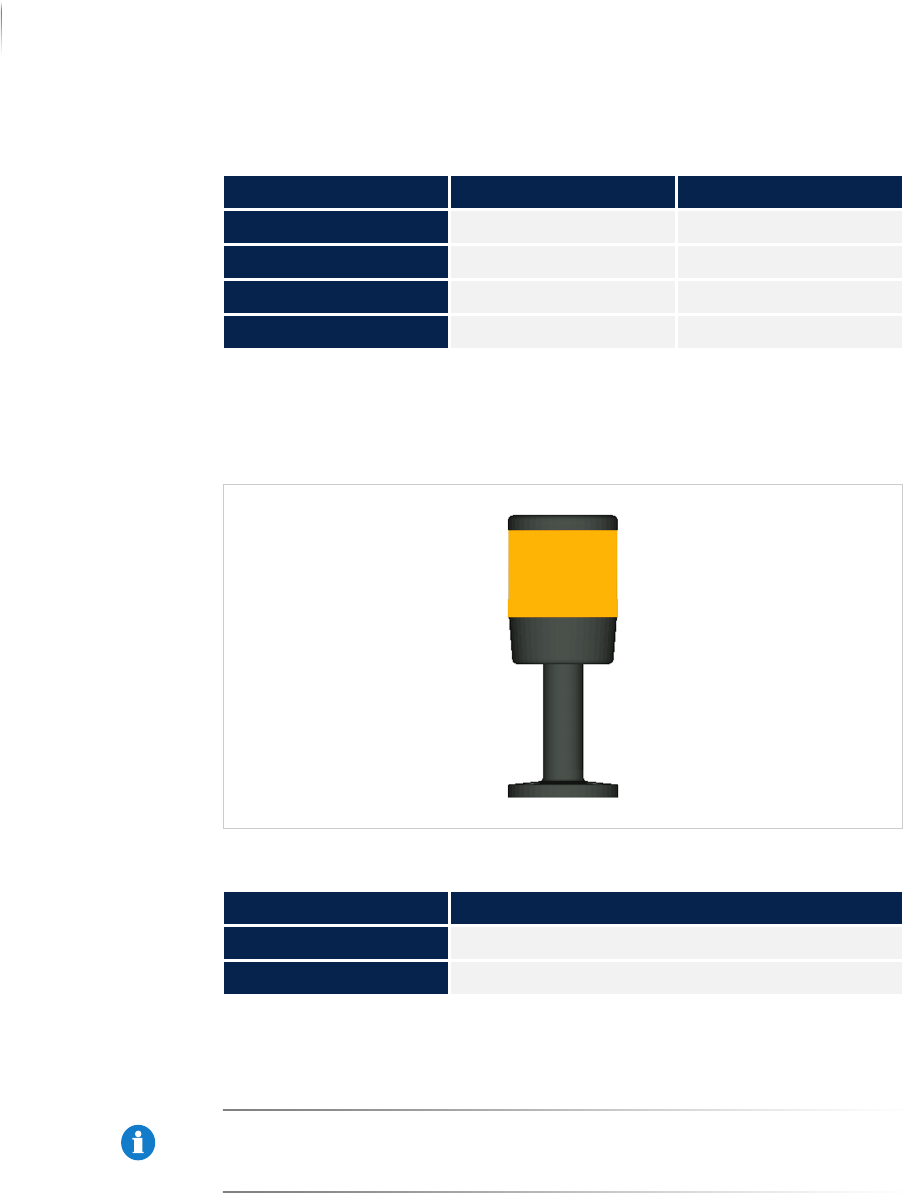
Additional
radiation
signal column
(optional)
Displays the generator operation of the X-ray system through an
orange light element. This signal column is available as an option
and meets the French standard NFC 74 100.
Additional radiation signal column
X-ray warning
lamp
Lights up when the inspection system is emitting X-rays during X-
ray operation.
NOTICE
The function of the X-ray warning and signal lamps is monitored. If
the warning lamp is defective, the X-ray current is prevented from
switching on.
Configuration of the X-ray signal lamp
Operating state Red Orange (optional)
Radiation operation on Lit -
Radiation operation off Doesn't light. -
Generator ON - Lit
Generator OFF - Doesn't light.
Configuration of the additional X-ray signal column
Operating state Light element orange
Generator ON Lit
Generator OFF not lit

Product description
System components
37
Inspection system X7056 | Operating manual |
Version 3.1 Rev.006| 2016-01-06 | 30.009.1930a
System components
In this section, important system components of the inspection
system are described.
The following components are described:
UPS (Page 37)
Network transformer (Page 37)
Transport system (Page 38)
AOI section positioning unit (Page 39)
AXI section positioning unit (Page 39)
Lift gate (Page 39)
Image acquisition control (Page 40)
XM camera head (Page 41)
XM 3D camera technology (Page 41)
Flat panel detector (FPD) (Page 42)
Sealed X-ray tube (Page 44)
UPS
The UPS is the uninterrupted power supply of the system
computers. The system has two UPS devices which continue to
provide the system computers with 230 V after EMERGENCY STOP
mode is actuated, please take appropriate protective measures.
NOTICE
Only one UPS is used in systems with XM 3-D camera technology
with GPU graphic card.
NOTICE
Only one UPS is used in systems with flat panel detectors with GPU
graphic card.
Network transformer
The system can optionally be equipped with a network trans-
former. This transformer is used to adjust the input voltage within
the range from 190V to 600V in 20V steps and allows the inspec-
tion system to be used worldwide. The wiring of the voltage to be
adapted can be taken form the current circuit plan.