X7056_Operating manual_en.pdf - 第40页
Product description System componen ts 40 Inspection system X7056 | Operating manual | Version 3.1 Rev.006| 2016-01-06 | 30.009.1930a Image acquisition control The function of the image acquisition control is to t ransfe…

Product description
System components
39
Inspection system X7056 | Operating manual |
Version 3.1 Rev.006| 2016-01-06 | 30.009.1930a
Printed circuit board clamping in the AXI transport cradle is accom-
plished by a coupled register drive, which allows the clamping
force to be adjusted. The weight of heavy PCBs can be compen-
sated for by increasing the clamping pressure of the integrated
springs.
There are two laser class 1 laser sensors - one in the front part of
the system between the AOI and AXI transport tracks and another
one to the right of the AXI transport track; the sensors trigger
when a PCB passes into a monitored area. This prevents potential
damage to the PCB from movement of the AXI transport track.
Configuration
of the trans-
port system
The inspection system is a single track system. The AOI transport
track passes the PCB to the AXI transport track with the help of a
belt drive.
Width adjust-
ment
The inspection system has an automatic, motor-driven rotational
width adjustment with an absolute measuring system. The trans-
port width is set during inspection plan creation or through the
product designation (barcode, 2-D data matrix code).
PCB stopper
A step motor actuates a latch, which acts as a stopper in its
extended position or is remains its initial position. An ultrasound
sensor queries the presence of a PCB.
AOI section positioning unit
The y-axis holds the image acquisition unit and positions it during
inspection over the various assemblies of the PCB to be inspected.
The AOI transport track moves the printed circuit board in the x-
direction.
AXI section positioning unit
The AXI transport track transports the printed circuit board in the
y-direction in the AXI section, where it is moved in the x- and y-
directions. The Z-axis allows the X-ray tube to be moved up and
down.
Lift gate
The lift gate separates the AOI and AXI sections. It opens so the
PCBs can be exchanged between the two sections. It isolates the
AXI section during inspection so no radiation leaks out.
Product description
System components
40
Inspection system X7056 | Operating manual |
Version 3.1 Rev.006| 2016-01-06 | 30.009.1930a
Image acquisition control
The function of the image acquisition control is to transfers camera
signals to the system computer.
Image acquisition control components:
VEB -102 (Page 40)
VEG-102 (Page 40)
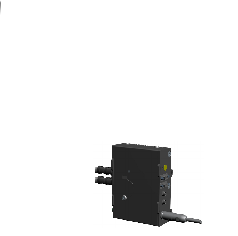
VEB -102
The single camera modules of the image acquisition unit are
connected to the head station VEB-102 which controls the image
acquisition. The head station concentrates the camera signals and
transfers the image data via optical fiber to the frame grabber
(VEG-102).
VEB -102
VEG-102
The optical frame grabber VEG-102 is a PCI express slot card and
transfers the acquired image data to the system computer.
Product description
System components
41
Inspection system X7056 | Operating manual |
Version 3.1 Rev.006| 2016-01-06 | 30.009.1930a
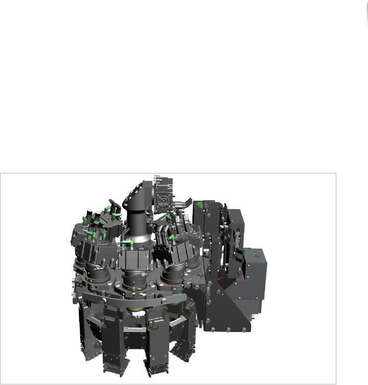
XM camera head
The XM camera head contains camera modules which generate the
image data and illumination modules which generate different illu-
mination types and directions. High power laser risk group 2 LEDs
are used for illumination. The optional fringe projector in 3D mode
allows to evaluate up to 8 image views from various angles, thus
performing 3D analyses in the entire field of view.
XM module
Orthogonal and AV (angled view) camera modules can be
combined into one XM camera head.
The following configurations of the XM module are possible:
XM4: 1 orthogonal camera and 4 angled cameras.
XM8: 1 orthogonal camera und 8 angled cameras.
Optional: XM 3D camera technology.
For additional information about technical specifications, variants
and combinations of camera modules, see „Technical specifica-
tions“ > „XM camera technology“ (Page 254).
XM 3D camera technology
With the XM 3D camera technology, up to 8 image views from
various angles are evaluated and 3D analyses are realized in the
entire field of view.
To calculate the height information, a projector unit must be addi-
tionally integrated into the XM module. This digital projector unit
projects various fringe patterns which are simultaneously captured
by the angled cameras.